


Understanding Northern Australia's Carbon Capture and Storage Potential: An Integrated Regional CO2 storage study

24 April 2014
Chris Consoli
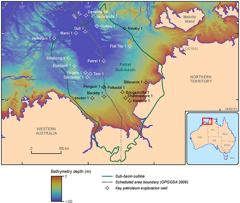
Figure 1: Location map showing
study region.
The completion of a recent study by Geoscience Australia indicates that the Petrel Sub-basin (Bonaparte Basin), offshore Northern Territory, is suitable for the geological storage of CO2. Following the Carbon Storage Taskforce report of 2009, the Petrel Sub-basin (Figure 1) was selected because of its prospectivity for CO2 storage and its proximity to current and future LNG processing plants near Darwin [1].
The Petrel Sub-basin CO2 storage assessment study is the first major CO2 storage assessment undertaken by Geoscience Australia as part of the Australian Government's multi-year program to assess highly prospective offshore basins for their CO2 storage potential. The Project was funded through the Australian Government's National Low Emissions Coal Initiative (NLECI).
Reservoir characteristics of the Petrel Sub-basin
For the CO2 storage assessment, the Petrel Sub-basin study adapted a regional assessment methodology similar to that used for oil and gas exploration (Figure 2).
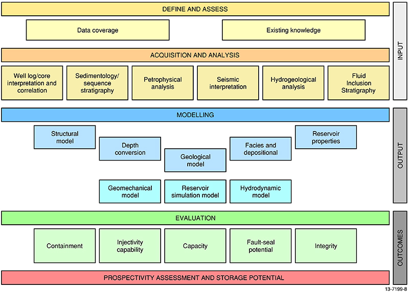
Figure 2: The overall workflow
undertaken as part of the Petrel
Sub-basin CO2 storage study.
The study focused on two Mesozoic-aged saline reservoir-seal pairs located over the central and eastern flank of the sub-basin. The lower reservoir-seal pair comprises the Jurassic Plover and Elang formations and the sand-dominated lower part of the Frigate Shale (Figure 3). The Jurassic saline reservoir is highly prospective due to its thickness (average 300 m) and fair to good reservoir properties for CO2 injection and storage. The conventional seal for the Jurassic reservoir is the upper section of the Frigate Shale, a sub-regional mudstone covering the central and northern parts of the sub-basin.
The Early Cretaceous Sandpiper Sandstone is a stratigraphically higher saline reservoir and in this study was identified as a highly prospective secondary target. It is generally thin (average 150 m) across the sub-basin, but has good to excellent reservoir properties for CO2 injection and storage. The Bathurst Island Group, in particular the Wangarlu Formation, is the primary seal for the Cretaceous saline reservoir and for the sub-basin in general. The seal capacity of the upper Frigate Shale and Bathurst Island Group is sufficient to contain the modelled CO2 column from injection into the reservoir over the expected life of the proposed Darwin LNG processing plants.
A geomechanical study revealed that, under the current stress regime, the major faults do not compromise the integrity of the seals.
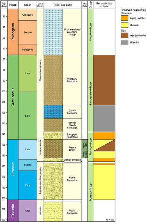
Figure 3: Mesozoic and Cenozoic
stratigraphy of the offshore
Petrel Sub-basin.
CO2 storage potential
Dynamic reservoir simulations show that the dominant CO2 trapping mechanism in the Petrel Sub-basin is migration-assisted trapping, with residual and dissolution trapping mechanisms the dominant process for permanent storage. CO2 injection reservoir simulations predict that a total of 420 MT of CO2 can be injected into the Jurassic reservoir at a rate of 14 MTPA over 30 years, a rate commensurate with the predicted emissions from the Darwin LNG hub in 2020 as estimated by the Carbon Storage Taskforce (2009) [1] (Figure 4).
During 30 years of injection, the simulated plume migrated laterally 5 km, and after the cessation of injection, migration slowed to around 12 m per year. After 100 years, the modelling indicated that over 50 per cent of the CO2 would be permanently trapped through residual and dissolution processes, and after 1,700 years, over 83 per cent of the total injected CO2 would be trapped. When taking into account the spatial and physical properties of the reservoirs and seals, the best estimate (i.e., P50) combined effective storage capacity of the two saline reservoirs was 15,930 MT.
Based on the geological evidence and modelling above, the Petrel Sub-basin was then sub-divided into regions showing the relative suitability for secure and permanent CO2 storage, with the most suitable regions located to the west and north of the sub-basin (Figure 5).
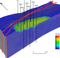
Figure 4: Plume migration simulation
in a small section of the Petrel
Sub-basin, showing CO2
plume saturation.
Industry will be able to use the report and associated datasets to make more informed decisions regarding the suitability of the site for CO2 storage.
Combined results
This multi-disciplinary, integrated assessment contributes to a wider program to develop a comprehensive understanding of Australia's total CO2 storage potential and adds vital information to support development of the carbon capture and storage industry.
The study report, Regional assessment of the CO2 storage potential of the Mesozoic succession in the Petrel Sub-basin, containing a series of supporting appendices, data packages and well composites, is available for download on the Geoscience Australia website.
References
[1] ^ Carbon Storage Taskforce, 2009. National Carbon Mapping and Infrastructure Plan - Australia: Full Report, Department of Resources, Energy and Tourism, Canberra.
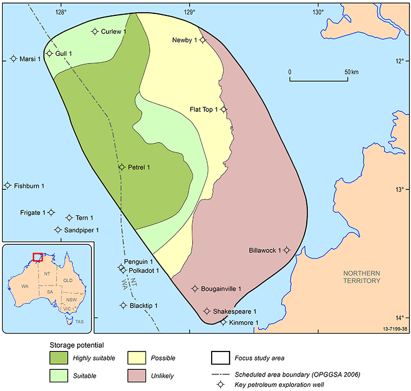
Figure 5: Map showing the CO2
storage potential of the Petrel
Sub-basin.