Section 2 - National Topographic Map Series (NTMS)
and General Reference Map Specifications
1. Scope of this document
This document provides the rules and guidelines for the generation of the Geoscience Australia 1:100 000 and 1:250 000 National Topographic Map Series products as well as smaller scale General Reference Map (eg 1:2 500 000) products. It includes the relevant standards expected for map accuracy, datum control, map generalisation principles, map symbology and masking rules, type selection and placement rules, type (font & size) specification and standard type abbreviations.
Conformance to these specifications will assure uniformity through all mapping elements and agencies engaged in the production and maintenance programs for these series.
2. Introduction
2.1 Use of Maps
The topographic map is a graphic representation of a portion of the earth's surface generalised to allow significant detail to be shown with clarity and without ambiguity. Detail is systematically plotted to scale on a selected map projection to present the horizontal and vertical position of topographic features in an identifiable and measurable form.
2.2 Map Accuracy
The term 'map accuracy' refers to the positional and vertical accuracy of information contained within the map. The term may also describe the quality and completeness of the information shown on a map. To the map user, the quality and completeness of the information is of prime importance and may take precedence over absolute positional accuracy. Thus the map maker must exercise maximum care in ensuring that the detail plotted is complete, correctly classified and portrayed with shape fidelity. Generalisation, although necessary in derived products, must be kept to a minimum.
2.2.1 Positional Accuracy
The positional accuracy of features on a map is an estimate of the degree to which the coordinates of that feature agree with the true values or values accepted as being true. The error in the position of a feature results from:
- The positional accuracy of the digital data used in the map production process (see Section 1 Chapter 3.7 Positional Accuracy)
- The errors inherent in the process of generalisation of the above data that forms part of the map production process. This error is applicable when the process of generalisation is independent from the source data capture/maintenance process. e.g. The use of a 'cartographic representation' of a feature maintained in its 'true position'.
The measure of accuracy given for topographic maps is the standard deviation.
The term 'well-defined points' is used to define those locations which can be accurately identified on the map. Most commonly the well-defined points used in tests are at feature intersections. Geoscience Australia has carried out both error analysis and field tests to verify the positional accuracy of features on the existing mapping.
While Geoscience Australia's positional accuracy measurements for topographic data are given to encompass a feature's entire spatial representation. Geoscience Australia restricts its statements of Topographic Map Accuracy to well defined points.
NTMS maps will comply with the following statements of planimetric accuracy:
At 1:100 000 scale, the summation of errors from all sources results in map detail with a standard deviation of 34 metres for well-defined features.
An alternative and equal way of expressing this error is:
- Not more than 10% of well-defined features are in error by more than 56 metres
At 1:250 000 scale, the summation of errors from all sources results in map detail with a standard deviation of 85 metres for well-defined features.
An alternative and equal way of expressing this error is:
- Not more than 10% of well-defined features are in error by more than 140 metres
General Reference maps will have no statement of map accuracy on the map layout however they must comply with the following statements of planimetric accuracy:
At 1:2 500 000 scale, the summation of errors from all sources results in map detail with a standard deviation of 850 metres for well-defined features.
An alternative and equal way of expressing this error is:
- Not more than 10% of well-defined features are in error by more than 1400 metres
At 1:5 000 000 scale, the summation of errors from all sources results in map detail with a standard deviation of 1700 metres for well-defined features.
An alternative and equal way of expressing this error is:
- Not more than 10% of well-defined features are in error by more than 2800 metres
At 1:10 000 000 scale, the summation of errors from all sources results in map detail with a standard deviation of 3400 metres for well-defined features.
An alternative and equal way of expressing this error is:
- Not more than 10% of well-defined features are in error by more than 5600 metres
2.2.2 Vertical Accuracy
The National Mapping Council of Australia Standards of Map Accuracy (2nd edition, 1975) stated in general terms that, 90% of tested contours and elevations interpolated from contours will be accurate to within one half a contour interval of their true height. A definitive statement on map accuracy, both horizontal and vertical, is included in the marginal information of all 1:100 000 and 1:250 000 maps.
2.2.3 Impact of Generalisation
The NTDB will be utilised by Geoscience Australia to capture, store and maintain features in their best possible positional accuracy and delineation. The data stored in the NTDB will then be utilised to generate products at various scales. This data will also be utilised by government as well as industry for modelling, strategic planning and information exchange.
The NTDB baseline data used to populate the model initially was the Series 3 TOPO250K GEODATA vector product, a nationally consistence cartographically generalised product covering the entire country at a minimum of 1:250 000 suitability. However, this baseline data has since been progressively updated with information of best possible positional accuracy and delineation derived from the NTICI program (nominally 1:25 000) as well as detailed theme revision and pinpointed maintenance based on infrastructure growth and decline. The NTDB should not now be considered a cartographically generalised database. Features in these databases should maintain the best possible planimetric accuracy available based on imagery, reference material and digitising method. When adding new features to, or editing existing features in the databases, the position should be as accurate as possible using the reference material available.
Minimal filtering of features will occur when capturing/including features into the NTDB. See Section 3 5.3 Cartographic Selection, Generalisation and Overlap for more details.
Geoscience Australia generates a variety of high quality scale-specific digital and hardcopy map/data products from the NTDB. As such every entity in the database must be considered for it's appropriateness at each of the standard scales utilised by Geoscience Australia and the associated cartographic enhancements needed for that scale.
Generalisation must and does occur to inherently allow a scaled version of reality. The process of generalisation is the most successful via a combination of artistic ability for feature composition and attention to detail in the understanding of the information being generalised.
The main controls on generalisation are map scale, spatial integrity and purpose. Generalisation is made up of 4 main activities, which are intrinsically interlinked:
- Selection
- Classification
- Simplification
- Symbolisation And Offsetting
The cartographic selection of NTDB features for each scale should be consistent between the map and data products. However some features will be represented on the map product in a textual capacity with no visual spatial representation (eg Mountain Ridges). While minimal filtering of features will occur on the underlying NTDB database, the cartographic selection of NTDB features for each scale will be identified by the use of two complementary fields 'UPPERSCALE' and 'DIMENSION'. See Section 3 5.3 Cartographic Selection, Generalisation and Overlap for more details.
Once cartographic selection has been resolved for each scale then cartographic classification, simplification, symbolisation and offsetting issues need to be resolved. These issues need to be resolved to derive high quality hardcopy and digital map products from the NTDB. It is important that the cartographic selection issues are addressed first to ensure cartographic classification, simplification, symbolisation and offsetting is not occurring against a feature not being included at that scale.
Where cartographic classification, simplification, symbolisation and offsetting is required to produce a high quality map products ,the Cartographic Representation Technology established under the appropriate symbol(scale) and symbol(scale)oride fields (eg Symbol100K and Symbol100KOride) should be utilised to provide alternative spatial representations.
As products progress from large scale (eg 1:100 000) to small scale (eg 1:10 000 000), the Cartographic Representation Technology may be used where defined in 'Appendix A- Feature Type Dictionary' geodatabases rules, to represent two or more feature types or attribute variations with the same symbology (eg At 1:250 000 saline coastal flat and swamp are represented using different symbol values but at 1:2 500 000 they utilise the same symbol value.)
While there is no official limitation to the amount of features, or feature types, (unless otherwise stated in Appendix A - Feature Type Dictionary ) to which cartographic generalisation activities of offsetting and simplification (eg void removal and line smoothing) can occur, it should remain restricted to only the minimum amount of displacement or simplification to create an acceptable cartographically product. Any movement of features which then cause them to exceed their minimum acceptable planimetric accuracies for the specific scale should be an exception rather than standard practice.
In addition standard Cartographic Representation symbols have been included to represent polygon/line features as point representations. Representation technology can also be used to smooth or generalise alternative spatial representatives without altering the underlying data held in the best available planimetric accuracy. Features may be located on the earth's surface in such a way that they cannot be separated at the scale of the map. To ensure cartographic clarity, either one feature is held in the correct position and the rest are displaced or when two or more features of the same type (e.g. powerlines) are close together they may be represented as a single feature. Within Cartographic Representation Technology, standard offset symbols have been established within the schema and should be used in preference to manual overrides as this will minimise impost on database memory. Examples of standard offsetting that will occur include offsetting railway features from road features and offsetting vertical obstructions from building points. Where possible, offsets should be restricted to within ((4 * Map Representation Scale)/5000)mm unless in an extreme case where multiple features require offsetting from each other.
The following information is applicable to All Scales.
When displacing one or more adjacent features, the higher a feature is on the list below, the more it should be attempted to maintain its correct position over those lower on the list. Natural features will be given precedence over constructed features. Features not on the list may be displaced unless otherwise stated in Appendix A Feature Type Dictionary or in the paragraphs above. In such circumstances the position of features on the list will be maintained over the position of features not listed. If two features need to be offset to one another and neither is listed, the position of the feature with greater landmark value will be maintained.
- Hydrographic lines such as coastlines, watercourses and lakes
- Principal roads
- Secondary roads
- Minor roads
- Vehicular tracks
- Railways
- Pipelines
- Canals
- Buildings
- Vertical Obstructions
For example, if a railway and road were coincident at the scale being produced, the railway would be displaced. Where two or three features are close and adjacent, one may be displaced by up to 225 metres at 1:250 000 scale and 90 metres at 1:100 000 scale. In the worst case when all these features are close and adjacent, one may be displaced by up to 675 metres at 1:250 000 scale and 270 metres at 1:100 000 scale.
Such displacement must maintain the correct alignment and spatial relationship of one feature to the other. Point features such as buildings in close proximity to linear features should be displaced in such a way that they retain, as far as possible, their positional relationship relative to other features. Where displacement of buildings will result in unnecessary clutter they may not be represented on the map. After displacement, these symbolised features will not remain within accuracy tolerances and therefore cannot be included in accuracy tests.
Cartographic Overlap issues will be resolved via a combination of masking and the resolution of inter-relationship rules.
2.3 Use of Map Symbols
Symbols and colours to be used are set out in Section 3 -Symbology of Polygon Edges, Appendix A - Feature Type Dictionary and Appendix S - Symbol Dictionary for Topographic Map Production.
2.3.1 Positioning of Symbols
Normally the centre of a symbol will correspond with the position of the centre of the feature on the ground and unless otherwise specified, the orientation of the symbol will correspond with the orientation of the feature on the ground.
When, for the sake of clarity, it is necessary to displace a symbol, the amount of displacement will be kept to a minimum. In situations where it is not possible to correctly position all the symbols for a group of features, only the symbol for the most important feature will be shown.
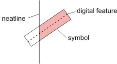
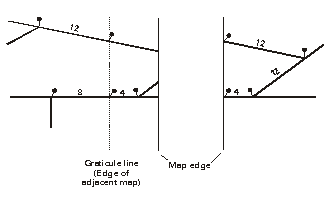
The symbology for linear features will not extend beyond the map neatline. Symbology for features that meet the neatline will be truncated at right angles to the feature within the neatline. Treatment of the symbology for linear features meeting the tile edge is shown below.
2.4 Map Projection and Grid
NTMS Maps published at the scales of 1:100 000 and 1:250 000 must use the Map Grid of Australia 1994 (MGA94) which is a Universal Transverse Mercator projection. Each map should be projected to the appropriate Map Grid Zone for its spatial location (see the delineation of the Map Grid Zones as per Appendix G - 1:250 000 & 1:100 000 NTMS Map Indexes).
General Reference Maps published at the scales of 1:2 500 000, 1:5 000 000 and 1:10 000 000 must use the Lambert Conical Conformal projection with two standard parallels of latitudes 18 Degrees South and 36 Degrees South as well as a Central Meridian longitude of 134 Degrees. A False Origin may be required dependant on the product.
The spheroid for all NTMS and General Reference hardcopy/digital Map products as well as NTDB derived data products is the Geocentric Datum of Australia 1994 (GDA94). A brief description of GDA94 plus Sample User Defined Coordinate System examples are available in Appendix M and additional information on GDA94 is available on the World Wide Web at: http://www.ga.gov.au/earth-monitoring/geodesy/geodetic-datums/GDA.html
2.5 Map Extents
Generally, each standard 1:100 000 map will cover a half degree of latitude by a half degree of longitude. For non-standard maps, extensions have been made to include large cities into one map and also to minimise the areas of sea contained on a map.
At 1:250 000 scale each standard map will cover a one degree of latitude by one and a half degrees of longitude. The maps will also have a 'bleed edge' of approximately three minutes to the north and around 5 minutes to the east. For non-standard maps, extensions have been made to include large cities into one map and also to minimise the area of sea contained on a map.
For a detailed list of non-standard 1:100 000 and 1:250 000 map areas, sheet extents and paper sizes refer to Appendix H.
The 1:2 500 000 General Reference Map will split Australia into 4 map sheets. The 1:5 000 000 and 1:10 000 000 General Reference Maps show the full extent of Australia.
2.6 Map Sheet Numbers and Names
The map indexes for both the 1:100 000 and 1:250 000 NTMS are detailed in Appendix G.
2.7 Datum for Map Control
Horizontal control coordinates are based on the Geocentric Datum of Australia - 1994 (GDA94). A brief description of GDA94 plus Sample User Defined Coordinate System examples are available in Appendix M and additional information on GDA94 is available on the World Wide Web at: http://www.ga.gov.au/earth-monitoring/geodesy/geodetic-datums/GDA.html
Vertical control values are based on the Australian Height Datum 1971, which is based on mean sea level 1966-1968.
2.8 Contour Interval
Generally, the standard contour interval for 1:100 000 scale maps is 20 metres. Occasionally omission of contours from the map (but not the data) will be necessary due to the nature of the terrain; variations to the standard interval will be advised on the map.
The 1:250 000 scale maps generally have a contour interval of 50 metres. Where omission of contours from the map (but not the data) is necessary due to the nature of the terrain in certain areas, variations to the standard interval will be advised on the map.
Contour intervals for General Reference Maps are selected for the best representation in the change of elevation over the entire landmass of Australia for more details see Appendix A - Feature Type Dictionary - Relief Feature Dataset
2.9 Masking
Geoscience Australia's Topographic Maps are generated via a CMYK composite file from which separates are derived. Colour separates are not generated directly from the data and therefore, as the majority of symbols do not have transparent components, the printing order controls the majority of masking issues. The printing orders and associated printing notes are detailed in 'Appendix W - Map Printing Orders'.
This chapter in conjunction with 'Appendix W - Map Printing Orders' provides rules so that masking of features is applied uniformly to reproduction material. These rules come into force where overprinting between symbols of different colour is undesirable and clashes between features are unavoidable; see Section 2 Chapter 2.2.3 Impact of Generalisation and Section 2 Chapter 5. Type Selection and Placement. These rules generally do not affect features in the production databases but will be applied in the processes that produce the reproduction material.
Specific instructions have been included in 'Appendix A - Feature Type Dictionary' as well as 'Appendix W - Map Printing Orders' and these will take precedence over these general guidelines. Care should be taken in reading Appendix A to differentiate between:
- Map rules which require masking (features to be broken) on the repromat but do not affect the features in the production databases;
- Map rules or general rules which require a feature to be symbolised to 0 in certain circumstances; and
- Data rules or general rules that control the presence of a feature in the production databases.
General rules for masking for all NTDB derived map products are:
- Unless covered by another general rule or a specific rule in Appendix A Feature Type Dictionary or 'Appendix W - Map Printing Orders', symbols higher in the print order will overprint (mask) symbols lower down the order. The only exception will be symbol with transparencies whose colours will be directly influenced by the symbol directly below them.
- Unless otherwise stated features will be masked with no gaps around the feature which is maintained.
- All other features will be masked for Route Marker - National, and Route Marker - State symbols and for Locality code 10 symbols.
Specific rules for masking to NTMS are:
- Solid black point, linear and area symbols and solid black pattern screens will be masked out for black type with a 0.2 mm gap around the type. Screened black features will not be masked for type.
Specific rules for masking to General Reference Maps are:
- Black linear features will be masked out for black type.
- All linear features except state borders and contours will be masked out for brown type.
- Black, blue and red linear features will be masked out for blue type.
- Linear features will be masked for annotation with a gap of between 0.25mm and 0.5mm around the type.
3. Information to be included
3.1 Information Internal to the Map
Those features specified in Appendix A Feature Type Dictionary (as applicable for a particular NTDB derived product) will be included on the map. The Feature Type Dictionary in conjunction with Appendix W - Map Printing Orders establishes criteria for inclusion of features. In complex areas care should be taken when adding new features to avoid clutter and ambiguity on the map.
3.1.1 Grid
For 1:250 000 scale maps, grid lines at ten thousand metre intervals of the Map Grid of Australia (MGA94) will be shown as specified on the relevant 1:250 000 NATMAP Series Format Sheet, Appendix B.
For 1:100 000 scale maps, grid lines at one thousand metre intervals of the MGA94 will be shown as specified on the 1:100 000 NATMAP Series Format Sheet, Appendix B.
Where the eastern bleed edge crosses the grid zone boundary or the sheet is extended to the east across a zone boundary, all data will be plotted on the primary zone. However, in the bleed or extended area the appropriate grid for the adjacent zone, properly georeferenced will be plotted rather than the primary grid. For example, the Bega or Dubbo 1:250 000 would be plotted on Zone 55 with the Zone 56 grid in the correct orientation plotted for the area east of 150 degrees east.
Where a map overlaps two or more zones the zones will be labelled at the boundary. The label will be in black UMC 7 point type all in caps. The label will be offset 2.5 mm from the graticule line where the zone change occurs.
Example (1:250 000 only)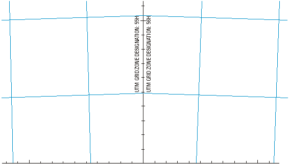
The 'UTM Grid Zone Designation' note will not be included on 1:100 000 scale maps.
General Reference Maps will include a graticule representation only with no associated map grid.
3.1.2 Graticule
For 1:100 000 scale maps, graticule lines at one minute intervals will be shown as specified on the 1:100 000 NATMAP Series Format Sheet, Appendix B.
For 1:250 000 scale maps, graticule lines at one minute intervals will be shown as specified on the relevant 1:250 000 NATMAP Series Format Sheet, Appendix B.
For 1:2 500 000 scale maps, graticule lines at 2 degree intervals will be shown. For 1:5 000 000 and 1:10 000 000 scale maps, graticule lines at 5 degree intervals will be shown.
3.2 Map Surround Information
Map Surround Information to be shown will conform to the format sheets at Appendix B.
4. Feature Names
Inclusion of names on the map does not imply approval by the relevant Geographic Names Board. However, an authoritative source should be used. Names appearing on the latest previous edition map at the same scale will be shown unless the named feature no longer exists. Additional names may be included from source material supplied, larger scale topographic mapping or from the controlling authority.
4.1 Type
Type styles and sizes to be used inside the neatline are specified in Section 2:
- Chapter 9 (1:100 000 Scale Type Specifications);
- Chapter 10 (1:250 000 Scale Type Specifications);
- Chapter 11 (1:1 000 000 Scale Type Specifications);
- Chapter 12 (1:2 500 000 Scale Type Specifications);
- Chapter 13 (1:5 000 000 Scale Type Specifications); and
- Chapter 14 (1:10 000 000 Scale Type Specifications).
Specifications for type styles, sizes and placement of grid and marginal information are contained in the appropriate format sheets in Appendix B (for both 1:250 000 and 1:100 000 scale).
5.Type Selection and Placement
Names and descriptive notes are integral components of a map, which are essential aids to the identification and qualification of features depicted on the map. They also provide information that cannot be shown by mapping symbolisation.
The final map should not be cluttered or ambiguous in content. Names and descriptive notes should be in a size and style relevant to the prominence and/or of the relative importance of the depicted features.
5.1 General
The proper selection and placement of type is of extreme importance and will not only benefit the map user but also the final appearance of the map. Poor or careless labelling of features can cause complications in map reading and negate the cartographic quality of the map.
Only standard abbreviations listed in Section 2 chapter 6, Authorised Abbreviations, will appear on the map.
Type selection and placement is governed by the nature, size and relative importance of the feature to be identified.
The examples provided illustrate preferred and less desirable approaches to map labelling, and in the interests of clarity, reflect optimum conditions. However, it must be realised that what is deemed incorrect or less desirable may be the only alternative under abnormal conditions.
Preferred positioning of type, as outlined in these specifications, is established to ensure a standard treatment of definitive labelling.
5.2 Selection of Names and Descriptive Notes
The selection of names and descriptive notes will be based on, and consistent with, the source material supplied by Geoscience Australia.
Names used on the latest previous edition map should be maintained unless there is strong evidence that they are incorrect or that the named feature no longer exists.
When considering the selection of names to be included on the map, every effort should be made to ensure that they are compatible with the particular map area, scale and use.
Factors that must be considered are:
- Date and reliability of the data,
- Density of names and detail,
- Legibility of the final product,
- Name placement relative to the depicted feature,
- The relative prominence and/or importance of topographical features within the area,
- The amount of descriptive notes necessary for clear portrayal, and,
- Consistency with adjoining maps and its related NTDB data attribution.
Common failings in the selection of names and descriptive notes include:
- Undue emphasis being given to minor features,
- Lack of consistency between similar features,
- Clutter,
- Ambiguous type placement, and,
- Inconsistency between adjoining maps.
5.3 Principles of Type Placement
This chapter establishes the basic rules for type placement. These rules are subject to exceptions. Frequently more than one rule may apply to a particular situation and these rules may be in conflict with one another. In these situations the overriding factors in assessing which rule(s) takes precedence are determined from a standpoint of graphic legibility and order of importance. The rules are given in their order of importance.
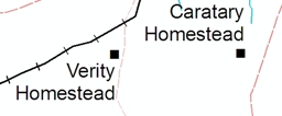
1. Internal type is positioned to assure immediate and unmistakable identification of the features being labelled. Where possible, labelling is placed in areas of sparse symbolisation to avoid obscuring important land formations and other detail.
Examples: 
Incorrect

Correct
2. For most features labelling should be placed in a straight line. Where a feature constitutes a simple curve, the associated type should be broken into its individual word components and each component positioned parallel to the part of the feature to which it is adjacent.
Examples: 
When labelling complex curves (e.g. rivers, ranges) the individual components are to be positioned so that they are parallel to the generalised shape of the feature. In both cases the components should appear to flow into one another and not have a disjointed appearance.
Examples: 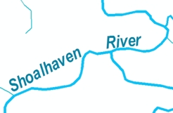
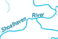
3. The maximum spacing between successive words of a feature name will be approximately one and a half (1½) times the length of the unspaced feature name. In many instances it will be practical to exceed the 1½ times rule providing word continuity is kept. Where practicable the word spacing should be the same for all words in a name.
4. Type positioned parallel to the easting grid line is aligned to read to its best advantage when viewed from the south neatline. The one exception to this rule occurs when adjacent features are nearly parallel and only one diverges from the perpendicular. In such cases, the direction of labelling is not reversed for the perpendicular feature.
Examples: 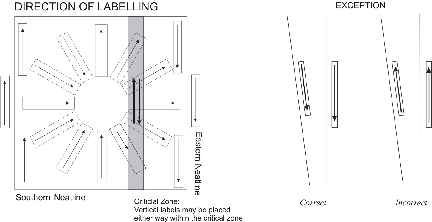
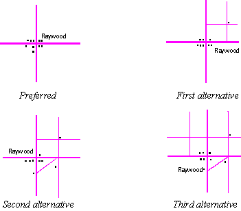
5. When labelling individual symbols or small concentrated groups of symbols comprising a single feature, the type is to be placed adjacent to the symbol or symbols and aligned parallel to the northing graticule lines. Some map extents will cover two or more zones. Horizontal type will always be aligned to the northing graticule lines of the zone in which the type is situated. Preferred and acceptable alternate positioning of type is illustrated in the following diagram. Numbers indicate priority order for the type position.
Example:
6. Instances will occur due to density of detail where type must be placed a distance from the feature to be identified. In these instances a feature pointer extending from the type to the feature is required. However, this practice is kept to a minimum.
Example:
7. An integral part of any map is the grid and/or graticule. As such it is preferable that type be positioned in such a manner as to avoid overprinting grid/graticule lines (particularly the northing grid lines) or numbers. At 1:100 000 the term grid lines for this point refers to the 10 000 metre grid line. Obviously this will be impossible in some cases (eg. ocean names, areas of dense detail etc.). In these cases it is preferable that type does not overprint grid/graticule intersections, as these are important measurement points when calculating grid references. When labelling spot features it is preferable that both the symbol and the relating type fall within the confines of the same grid square. Where this is not possible due to length of type, the type should be positioned so that the grid/ graticule line does not impair its legibility. In extreme cases the grid/graticule may be broken to accommodate type.
Examples:
8. Where possible, overprinting of type and detail, which print in the same colour, is to be avoided. In unusual cases, particularly where smaller type sizes are involved, it is necessary to block out features when legibility of type would otherwise be impaired.
The overprinting of type (letter touching letter) regardless of printing colour is not permissible in any circumstances.
9. Type should be positioned to avoid overprinting features that are to be printed in black, especially where such features are parallel to the type. When it becomes necessary to position labelling across linear features that are at right or near right angles to one another, the type is placed so that the letters of the label clear the perpendicular features.
Examples:
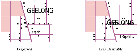
10. Names consisting wholly of capital letters are centred within the area being identified, built-up areas excepted. If the area is extensive letter spacing is desirable.
Line spacing between words (leading) to be equal.

EXAMPLE: Type is generally centred, if possible, when placed within the area feature.
If the name does not fit within the area then the following rules apply:

EXAMPLE: Type is left justified when placed to the right of the area feature.

EXAMPLE: Type is right justified when placed to the left of the area feature.
If the area is extensive, letter spacing is desirable. When spacing type, the spacing between letters is not to exceed four (4) times the point size of the letters. Where letter spacing is used and the name consists of two or more words, the space between words is equal to three (3) times the space between the letters. Type that is letter or word spaced must be positioned so that the name stands out distinctly as a complete name. In congested areas, caution is advised on the use of maximum spacing since the continuity of names may be disrupted.
EXAMPLE:
RESERVE (12 point)
R E S max letter spacing 36 point (3 times type size for 2 words)
![]()
![]()
36 point
It is not permissible to letter space names shown in both capital and lower case lettering.
Descriptive labels should be centred within or adjacent to the features area. Labels are aligned parallel to the northing graticule line; however in unusual cases they may be positioned to follow the general shape of the feature.
11. Alternate names are preferably positioned below the primary name in the case of point or area features, and following the primary name in the case of linear features. Alternate names are shown in parentheses and in the same style of type as the primary name, but one point size smaller. An exception to this Rule occurs when the primary name is in the smallest type available or is in the smallest legible size.
In cases where the primary name includes a generic term (eg. 'River', 'RANGE'), the alternate name is placed between the primary and the generic term. Single word alternatives are placed adjacent to the primary name.
Examples:

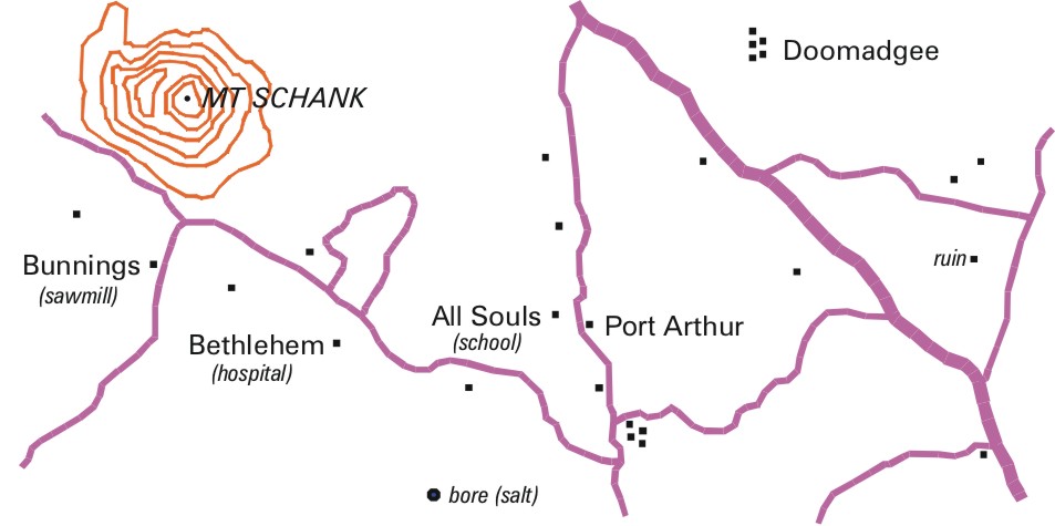
12. Descriptive terms may be added for the purpose of clarifying a primary name (eg. 'ruin', 'walled', 'abandoned'). For point and linear features descriptive terms are enclosed by parentheses. The parenthesised type is preferably centred directly below or positioned immediately following the primary name it clarifies.
A descriptive term included where there is no primary name or label will not be parenthesised.
All descriptive labels on point and linear features, parenthesised or not, will be shown entirely in lower case lettering and italicised.
See Section 2 Chapter 5.7 Descriptive Notes on Area Features for handling of descriptive notes on area features.
Example:
13. Punctuation is omitted except for hyphens and apostrophes that are integral parts of official designations. Full stops are not to be used with abbreviations.
14. At 1:250 000 feature names should be placed so as to be wholly within or wholly outside the areas of overlap within adjacent maps. At 1:100 000 no annotation should exist in the bleed (map overhang).
15. Case sensitive names: Lower and uppercase letters will be used if they are an integral part of the proper name. For example: McLarty Hills or McLARTY HILLS; St George or St GEORGE. In all instances, the lower case letter will be aligned at the bottom of the other letters.
5.4 Populated Centres
Populated centres are depicted on the map by either individual buildings, clusters of buildings, built up areas or built up area symbols. The type size and style for place names are selected to fit predetermined classifications relative to population.( See Section 2 Chapter 9 (1:100 000 Scale Type Specifications),Chapter 10 (1:250 000 Scale Type Specifications) ,Chapter 11 (1:1 000 000 Scale Type Specifications) ,Chapter 12 (1:2 500 000 Scale Type Specifications) ,Chapter 13 (1:5 000 000 Scale Type Specifications) or Chapter 14 (1:10 000 000 Scale Type Specifications) as appropriate.)
When identifying a built-up area, it is preferred that the name be positioned entirely within the limits of the area, provided that the legibility of type or continuity of cultural features is not impaired. When preferred positioning cannot be adhered to, the name is placed adjacent to the feature and aligned in accordance with Section 2 Chapter 5.3 rule 5.
When naming localities, the term 'mission' and 'homeland' should be avoided - refer to Geoscience Australia for correct name. Indigenous community names also need to be checked against geographic source information as many have changed in recent years. The word 'Community' may be used if it is the official name, eg: Burringah Community.
The names for localities represented by concentrated groups or clusters of building symbols are positioned in close proximity to the subject area. Type is preferably placed at, or near, the junction of the most heavily travelled route(s) passing through the populated centre.
Example:
A locality comprised of several individual homesteads requires unique treatment in that the name is placed over the approximate centre of the area covered by the locality. It is preferable that the type be placed parallel to the northing graticule line
Example: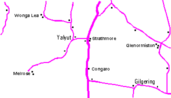
Instances will occur, particularly in flat areas, where localities are comprised of semi-scattered buildings strung out along the major communication routes. When labelling this type of locality the name is placed adjacent to the junction of the main thoroughfares bisecting the locality.
Example: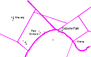
In some rural areas, localities are comprised of widely dispersed buildings. These areas are often identified by references to prominent local features. Where this occurs, the name is positioned in the immediate vicinity of the feature referenced and extended toward the general area it serves to identify.
Example: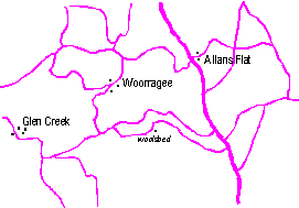
Proper names of well-known sections within a city, or outlying suburban areas, are shown in populated place type. The type is shown in capital and lower case lettering and is centred in the area concerned. The type size is scaled relative to the size of the subject area.
Names of places located along shorelines are placed entirely in the open-water area. Where developed areas are located adjacent to (but inland from) the shoreline, the name is placed entirely on the land area.
Examples:
5.5 Point Features
An individual symbol or small concentrated groups of symbols may be labelled. The labels for features are usually descriptive. When labelling point features the type is positioned in accordance with Section 2 Chapter 5.3 rule 5. Where there are large numbers of instances of a feature, a general descriptive note may be included so as to reduce clutter, for example 'pools'. Care will be taken to avoid ambiguity when this is done.
Examples:
5.6 Linear Features
Linear features include such items as roads, railways, power transmission lines, pipelines, double and single line watercourses, and similar features. When labelling linear features, it is preferable that the type be placed parallel to and above the upper side of the symbol as viewed from the south neatline.
Names for linear features are never letter spaced or extended. When a name placed at the middle point of a linear feature does not identify it sufficiently, the name is repeated at appropriate intervals to further clarify the symbol.
Where possible, labelling is placed along the straight segments of linear features rather than the curved portions. Where there is no alternative but to label the curved portions, type is to be positioned in accordance with Section 2 Chapter 5.3 rule 2.
When labelling boundaries, the names are placed on the side of the boundary that corresponds with the area being identified. It is preferred that the names be positioned adjacent to one another and parallel to the boundary symbol separating them.
Examples:
In the placement of type referring to drainage features, "U" or inverted "U" shaped labelling is to be avoided. When labelling double line watercourses, it is desirable to have the names within the shorelines, provided the feature is wide enough to accommodate the entire name. Type is never positioned partially in or out of double line streams.
Example:
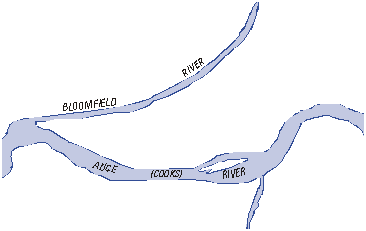
When labelling watercourses that are predominantly double line, the name is shown wholly in capital letters. The names for single line watercourses are shown in capital and lower case lettering.
Examples:
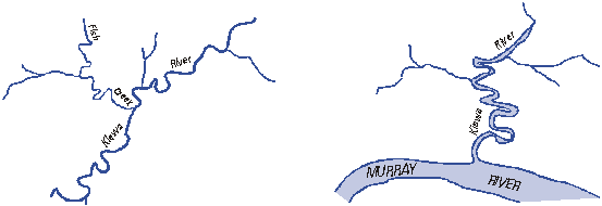
Where a feature is too small to show the identifying type in its entirety, the authorised abbreviation given in Section 2 chapter 6, Authorised Abbreviations, is to be used.
5.7 Descriptive Notes on Area Features
Included in this category are features that are indicated only by descriptive labelling or where a descriptive label gives more information on the feature. The type should be centred within or adjacent to the features area. Labels are aligned parallel to the grid; however, in unusual cases they may be positioned to follow the general shape of the feature. See Appendix A Feature Type Dictionary – Recreation Areas (Feature Class), Distorted Surface, Mine Area and Outcrop. Descriptive notes may also be used for areas not stored as features in the database.
For unnamed and otherwise unlabelled area features the descriptive notes will be as specified in Section 2 Chapter 9 (1:100 000 Scale Type Specifications) and Section 2 Chapter 10 (1:250 000 Scale Type Specifications). For large areas the descriptive note may be repeated. For named or otherwise labelled areas such as reserves the descriptive notes will be in the same style and size as the name.
Example: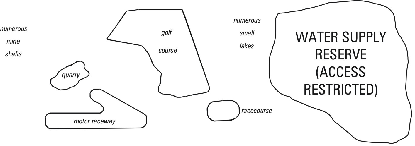
5.8 National Parks and Similar Features
When labelling national parks and similar features, it is preferable that the type be centred within the feature, space permitting. When the area is extensive, letter spacing is desirable.
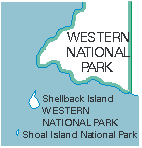
Descriptive labels such as (ACCESS RESTRICTED) will be shown in the same type size as the administration area name label (see Example 2).
It is not uncommon to find smaller designated land tracts as integral parts of larger designated land areas. Labelling of the smaller designated areas is to be in a type size appropriate to the size of the area.
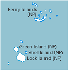
Where a national park or other administration area consists of several separate areas, each area is named. In cases where a national park or other administration area includes several offshore islands or both mainland and offshore island(s), type pertaining to the national park or other reserve will also be placed below the island name in a size relative to the size of the island. Where a reserve includes areas of both land and sea the type will be placed in which ever is the larger of the land or sea area (see Example 3).
Situations may occur where a large number of islands form a national park, or administration area, and the islands have the same name as the national park or administration area. Where the addition of the park or administration area name to each island would result in clutter, an abbreviation (eg '(NP)') may be added after the island names. In this case the name of the administration area must appear at least once on the map (see Example 4).
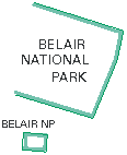 |
 |
 |
 |
| Example 1 | Example 2 | Example 3 | Example 4 |
5.9 Route Markers and Distance Indicators
Route markers are centred on their respective road symbols and aligned parallel to the graticule line. Route markers are positioned so as to avoid grid lines, linear drainage symbols, and congested map detail. All other detail is blocked out of route markers.
National Route Marker Example:
The following are guides for placement of route markers to assure maximum effectiveness.
- Route markers are positioned in areas free of congested map detail.
- On roads that continue onto adjoining sheets, route markers are shown close to the map neatline.
- Route markers are shown close to populated places.
- Route markers are shown as often as required to ensure identification and reader continuity.
- Route markers are shown in the vicinity of road junctions and intersections.
- Individual route markers are shown for each route value when roads have a designated combination of two or more routes. When this occurs, the markers should be shown close together.
Kilometric distance indicators and the associated distances will be placed to avoid ambiguity and allow the calculation of route distances. Particular care should be taken around the map edges with the placement of kilometric distance indicators. Placement of indicators should be consistent between adjacent sheets and allow calculation of distances to continue from one sheet to another.
1:250 000 map distance measurement
A Kilometric Distance Indicator will be placed at the intersection of the road and the neatline on the south and west edges when associated with a destination arrow. For the north and east edges, a Kilometric Distance Indicator will be placed at the intersection of the road and the graticule line at the inner edge of the map bleed, and preferably will be aligned so that the symbol falls within the bleed edge. Where there is a destination to be indicated within the bleed edge, a road distance will be given to that destination from the graticule line. A MapNumber associated with a Kilometric Distance Indicator will not need to be maintained at 1:250 000.
1:100 000 map distance measurement
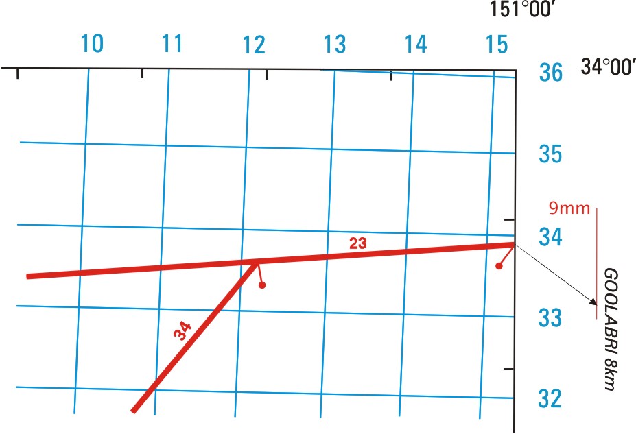
A Kilometric Distance Indicator will be placed at the intersection of the road and the neatline for all map edges when associated with a destination arrow, and aligned so that the symbol falls within the map sheet. A MapNumber associated with a Kilometric Distance Indicator will only be maintained for those Kilometric Distance Indicators falling on a neatline.
| 1:250 000 Scale Example: | 1:100 000 Scale example: |
 |
|
5.10 Relief Features
Features included in this category are: mountains, mountain ranges, ridges, valleys, plains, gorges, peaks, hills, bluffs, tors, and topographic surface characteristics.
In labelling relief features that are extensive in size, the type is positioned slightly above the axis of the landform as viewed from the south neatline. The name may be letter spaced and is aligned parallel to the general formation of the feature.
Example:
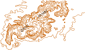
The names for narrow valleys, gorges, and similar features are preferably placed on the upper side of, and parallel to the axis of the feature identified.
The words 'Mount' and 'Mountain' will be abbreviated in all cases for these relief features as per the following examples; 'Mount Donald' would be shown as MT DONALD and 'Glendower Mountain' as GLENDOWER MTN on the map. Where 'Mount' and 'Mountain' form part of the name for a Range relief feature, this abbreviation will not be applied. For features other than relief features, the normal rules for use of abbreviations apply.
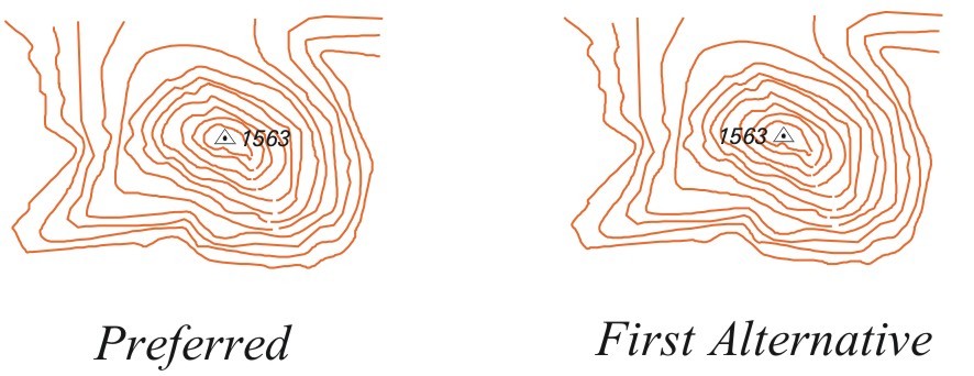
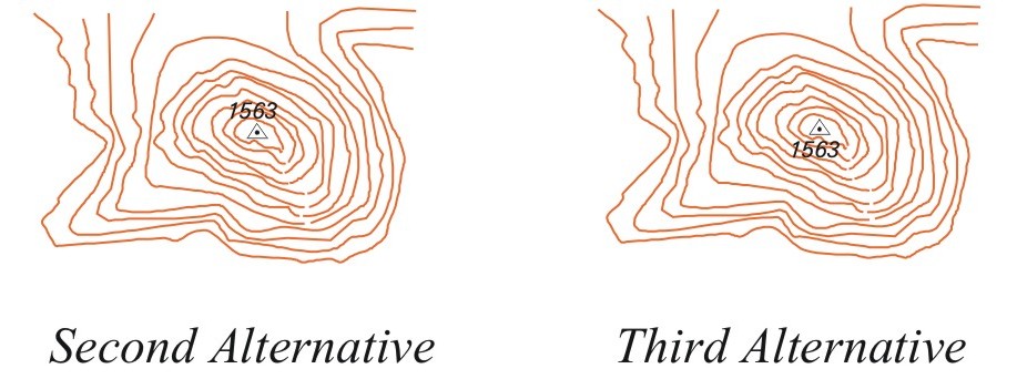
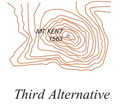
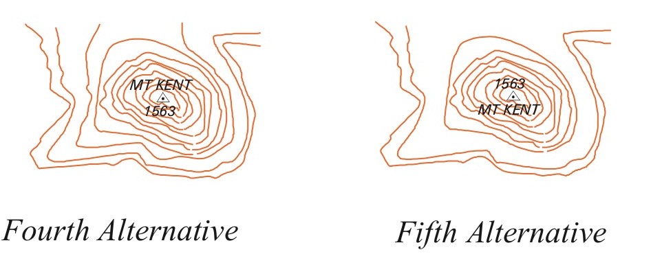
When labelling hills, peaks, pinnacles, and similar features, the type is placed in accordance with Section 2 Chapter 5.3 rule 5 provided it does not obscure other prominent detail, and the continuity of the relief remains unchanged. To avoid ambiguity, a spot elevation symbol may be used. Preferred and acceptable alternate positioning of names is established by the following examples:
Examples:
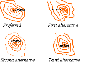
Terms describing the nature of terrain, such as "gilgai" or "lava" are required when such features cannot be precisely identified with reference to the map symbol legend or where definitive labels must serve as the only means of area identification. When supported by a symbol pattern, labels are centred within the subject area. When labelling large areas void of distinctive symbolisation, the term is repeated as often as necessary to properly define area coverage and the approximate limits of the feature.
5.11 Contour Values
Contour values provide a convenient means of reading elevations portrayed by contour lines. The number and location of contour values is governed by the nature of the terrain, density of contours, and the number of horizontal control points and spot elevations. Areas of complex topography require a greater number of contour values than do areas of simple terrain.
Contours above the datum plane are labelled with positive numerals bearing no prefix. Contours below the datum plane are prefixed with the negative sign ( - ). Contours that are level with the datum plane are labelled with the numeral 0 (zero). Contours are not broken for contour values.
Contours will be labelled with the values reading uphill. Preference is given to them being legible from either the south or east neatline. Values for negative and zero contours are positioned in the same manner.
In the majority of cases, preferential treatment should be given to labelling index contours. In flat areas, however, most contours should be labelled so as to facilitate interpretation of the terrain.
Contour values are centred on the axes of contour lines, and are not positioned in the immediate vicinity of horizontal control points, bench marks, or spot elevations.
Examples:
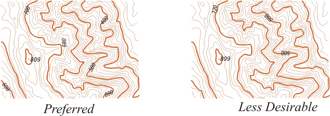
When labelling contours, sets of numerals are positioned so that a mechanical or stepladder like appearance is avoided.
Examples:
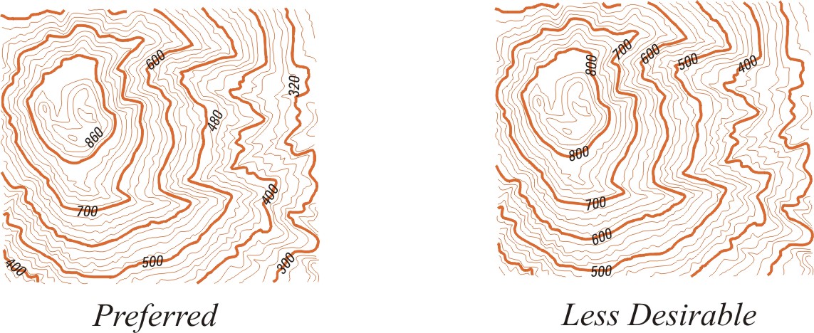
Contour values are most effective when positioned near the ends of spurs, the sides of ridges, and at pronounced changes in topography. Under no circumstances are values positioned in mirror like sequence on each side of a particular ridgeline or landform.
Examples:
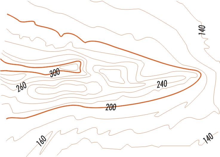
Contour values are evenly distributed throughout the map sheet thus enabling the user to determine elevation without a prolonged search for reference points. When labelling contours portraying major landforms, values are repeated at distances of 10 to 15 centimetres. Contour values will be positioned clear of all other detail.
Space permitting, contour values are added to auxiliary and depression contours wherever they are shown.
Isolations should be labelled where possible.
Sufficient values should be positioned near the neatline so that it is possible to determine the value of any contour crossing the neatline. Descriptive labelling will always take precedence over contour labelling.
5.12 Spot Elevations
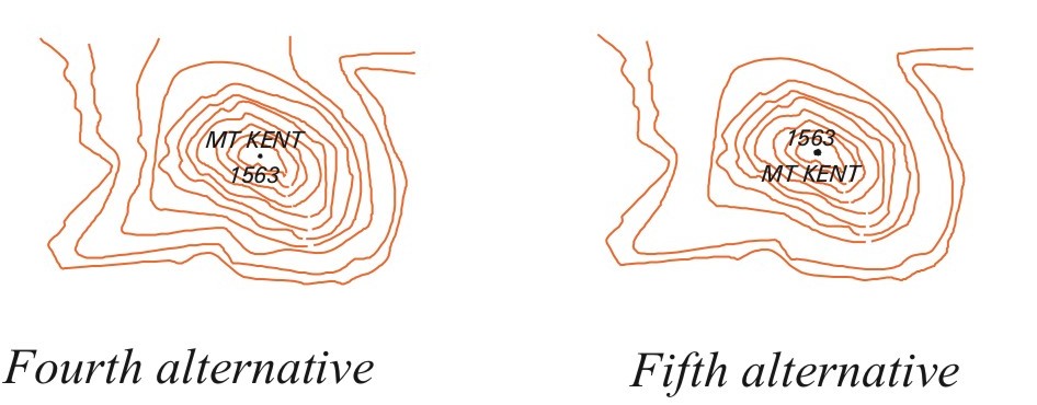
Spot elevation values are positioned in close proximity to the symbol they identify. Where possible, the elevation values are placed to avoid obscuring features of importance to the map user; for example, peaks, ridges and saddles. It is preferred that the values be positioned to the right of the defined point with the centre of the numerals aligned with the horizontal centre of the referenced symbol.
Examples:
Elevation Only
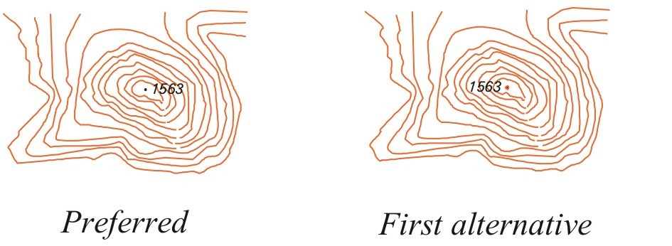
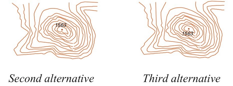
Elevation and feature name

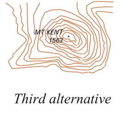
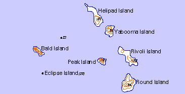
Instances will occur where spot elevations are provided for islands too small to accommodate the values. In such cases the value is positioned adjacent to the island and aligned in accordance with the previous paragraph. When the island is identified by a proper name, the value is shown at the end of the name and in parenthesis.
Examples:
5.13 Horizontal Control Points
Values of horizontal control points are positioned in accordance with Section 2 Chapter 5.3 rule 5.
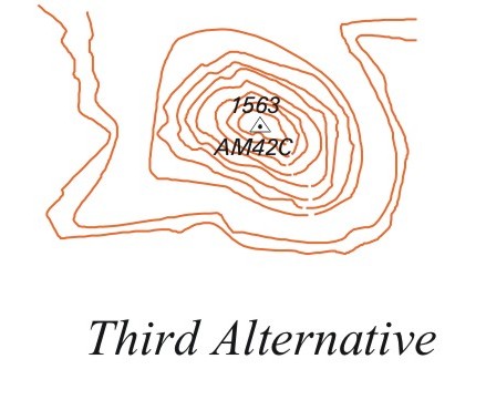
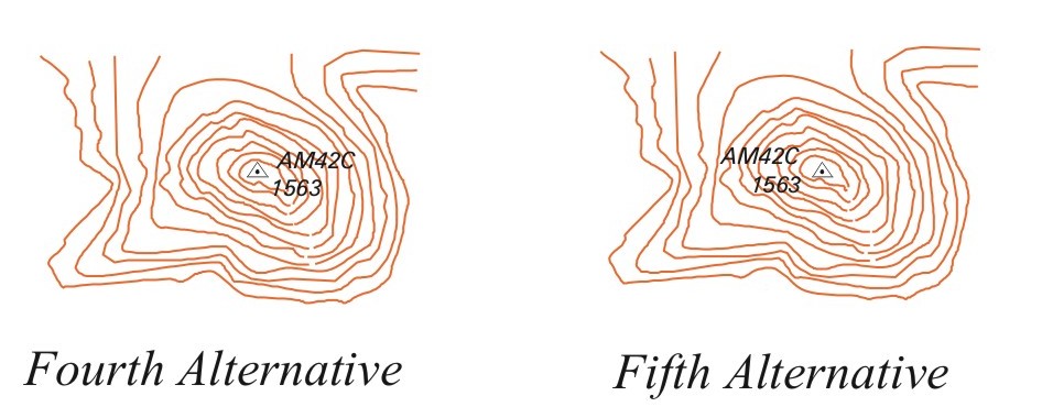
The following outlines the procedure for labelling and portraying horizontal control points:
- Only three types of information can be added to a horizontal control point:
- elevation,
- name of the feature where horizontal control point is located, and
- alphanumeric code
- Only two of the above are shown at any one time.
- The order of importance of the type of information is as listed in (1) above.
- A horizontal control point can be shown provided one of the pieces of information above is available.
- A horizontal control point is not to be shown regardless of classification, if no information is available.
- Destroyed horizontal control points are not to be shown, however, if height and co-ordinates are known, a spot elevation and dot may be shown, and
- The horizontal control point identification name is not to be shown.
Examples:
Elevation Only
Elevation and feature name

Elevation and alphanumeric identifier

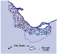
5.14 Coastal Hydrographic Features
Coastal hydrographic features require the use of descriptive notes. Notes will appear wherever they convey information pertinent to the map user or where they clarify situations that could otherwise be confusing. Definitive labels for coastal hydrographic features are positioned as close to their precise location as map detail will allow. The type is positioned to avoid overprinting grid lines and hydrographic map symbols. Where two different characteristics are identified in the same location, such as mud and sand, they are centred one over the other.
Example:
5.15 Capes and Islands
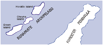
In labelling capes and islands that are of extensive size, the type is centred within the land area and positioned parallel to the northing graticule line and, if necessary, letter spaced.
The names for peninsulas and island chains are placed parallel to the general formation of the feature. Where possible, the type identifying peninsulas is positioned within the land area.
Example:
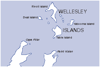
The names for capes, points, and small islands are placed in the open water adjacent to the feature. Wherever possible, the type is placed to the right of the feature. Names are always positioned to avoid overprinting the shoreline.
Example:
5.16 Waterbodies and Watercourses
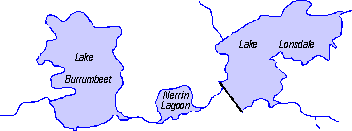
In labelling bodies of water whose limits can accommodate the entire name, the type is centred within the limits of the feature. Names are aligned parallel to the northing graticule line. When labelling large expanses of water, letter spacing is desirable.
Example:
When labelling small lakes and ponds, the names are positioned in accordance with Section 2 Chapter 5.3, rule 5.
The identifying names for marshes, swamps, bogs, and similar features are centred within the limits of the feature defined. The type is preferably aligned parallel to the northing graticule lines, and, when the area is extensive, letter spacing is desirable.
Example:

For rules on labelling Watercourses and Anabranches, refer to Section 1 chapter 3.8.1 Names and Section 3 chapter 6.9.3 Naming Watercourses, Anabranches, and Connectors.
5.17 Vegetation Features
The proper names for forests and rainforests are shown wherever there is sufficient space to accommodate the labelling. When labelling vegetation features, the type is centred within the overall limits of the area to be identified. The names are aligned either parallel to the northing graticule lines or placed to follow the general shape of the feature. When labelling large expanses of vegetation, letter spacing is desirable.
6. Authorised Abbreviations
This listing is in alphabetical order by term. The term is given first followed by the abbreviation.
Unless otherwise stated, abbreviations will only be used where use of the full word would cause clutter or ambiguity.
The case of the abbreviation will be the case specified for the feature name in Section 2 Chapter 7. Type Size Selection Criteria.
| Term | Abbreviation |
|---|---|
| Abandoned | Aband |
| Aeronautical | Aero |
| Anchorage | Anch |
| Approximate | Approx |
| Archipelago | Arch |
| Australia | Aust |
| Avenue | Ave |
| Bay | B |
| Beach | Bch |
| Bench Mark | BM |
| Boundary | Bdry |
| Bridge | Br |
| Brook | Bk |
| Building | Bldg |
| Built-up Area | BUA |
| Cape | C |
| Cemetery | Cem |
| Channel | Chan |
| Construction | const |
| Creek | Ck |
| Department | Dept |
| East | E |
| Electric | elec |
| Elevation | elev |
| Estuary | Est |
| Expressway | Exwy |
| Factory | Facty |
| Fire Station | FS |
| Forest | For |
| Four Wheel Drive | FWD |
| Freeway | Fwy |
| Gulf | G |
| Great | Gt |
| Ground | gnd |
| Group | Gp |
| Harbour | Har |
| Head | Hd |
| Headland | Hd |
| Height | ht |
| Highway | HWY |
| Homestead | HS |
| Hospital | Hosp |
| Inlet | In |
| Intermittent | Int |
| Island | Is |
| Islet | It |
| Junction | Junc |
| Lagoon | Lagn |
| Lake | L |
| Landing | lndg |
| Light | Lt |
| Metre(s) | m |
| Millimetre(s) | mm |
| Mount | Mt Use for relief features only. No abbreviation is to be used for Mount when part of a Range name or a Place name. Examples: MOUNT LOFTY RANGES Mount Barker |
| Mounts | Mts, Use for relief features only. |
| Mountain | Mtn Use for relief features only. |
| Mountains | Mtns Use for relief features only. |
| Mouth | Mth |
| National Park | NP |
| Nature Reserve | NR |
| North | N |
| North-east | NE |
| North-west | NW |
| Number | No/no |
| Orchard | orch |
| Outstation | OS |
| Passage | Pass |
| Peak | Pk |
| Peaks | Pks |
| Peninsula | Pen |
| Perennial | Per |
| Permanent | perm |
| Place | Pl |
| Plantation | pltn |
| Plateau | Plat |
| Point | Pt |
| Police Station | PS |
| Position | posn |
| Post Office | PO |
| Prohibited | prohib |
| Promontory | Prom |
| Quarantine | Quar |
| Railway | Rly |
| Range | Ra |
| Recreation Reserve | Rec Res |
| Reserve | Res |
| Reservoir | Resvr |
| River | R |
| Road | Rd |
| Rock | Rk |
| Rockhole | RH |
| Runway | Rwy |
| Saint | St |
| School | Sch |
| South | S |
| South-east | SE |
| South-west | SW |
| State Forest | SF |
| Station | Stn |
| Stock Route | SR |
| Strait | Str |
| Street | St |
| Submerged | submd |
| Suspension | susp |
| Tank | Tk |
| Temporary | temp |
| Tower | Twr |
| Underground | Ugd |
| Vehicle Track | VT |
| Waterhole | WH |
| Waterholes | Whs |
| Water Tank | Wtk |
| West | W |
| Wharf | Whf |
| Wreck | Wk |
| Yard | Yd |
7. Type Size Selection Criteria
The type sizes and styles prescribed in the following Type Specification sections are to be maintained. In exceptional circumstances, when space prohibits the use of a prescribed size, or the size indicated would distort the relative importance of the feature, a more appropriate size is to be selected.
The appropriate type size will be based on the size of the feature as it appears on the face of the map. For example, if the Murray River appears as one long feature across the face of the map and warrants a large type size, and a small section reappears at the neatline, the type size for the small section is based on the length of that small section. Similarly, for area features the type size will be chosen according to the area of the section that is being labelled.
All type is to be shown using the CMYK four colour process (ie. combinations of Cyan, Magenta, Yellow and Black).
All type (unless otherwise specifically stated in this document) is to be shown in Black
ie. colour C 0% M 0% Y 0% K 100%
8. Type Style (Font) Abbreviations
In the following Type Specification sections, styles are abbreviated as follows:
| Font Abbreviation | Font Description |
|---|---|
| A | Arial |
| AI | Arial Italic |
| AB | Arial Bold |
| ABI | Arial Bold Italic |
| AN | Arial Narrow |
| ANI | Arial Narrow Italic |
| ANB | Arial Narrow Bold |
| AB | Arial Black |
| ABI | Arial Black Italic |
| PL | Palatino Linotype |
| Case abbreviation | Case description |
|---|---|
| C | all capitals |
| CL | capitals and lower case |
| L | all lower case |
| N/A | Not Applicable |
Alternative type styles are:
- Acceptable substitute for Palatino is Stymie or Rockwell. Such substitutions will be consistent across a map sheet.
- Times Bold Italic (see Map Layout Guide requirements) may be substituted by Times New Roman Bold Italic.
The following digital representations of the type may vary from that required depending on system specifications. Hard copy representations of type will be supplied if required.
9. 1:100 000 Scale Type Specifications
9.1 Cultural Features
| ROADS, RAILWAYS AND RELATED FEATURES | 1:100 000 | ||
|---|---|---|---|
| FEATURE DESCRIPTION / CRITERIA | POINT SIZE |
STYLE | CASE |
| Dual carriageway and Principal Roads |
6 | AI | C |
| Other roads | 5 | AI | C |
| Descriptive text notes can be used in areas where many private roads have restricted access, or cleared/seismic lines | 8 | AN | C |
| Foot track Descriptive text (with name included) Descriptive text (without name) |
6 6 6 |
ANI ANI ANI |
CL CL L |
| National and state route marker | 6 | AN | C |
| Road Junction | 8 | AN | CL |
| Kilometric distance (Red -C 0% M 100% Y 100% K 0%) |
6 | AB | N/A |
| Named bridge/tunnel | 6 | AN | CL |
| Railway line | 6 | AI | C |
| Named: Railway station, road/railway causeways, siding, marshalling yard; crossing, landing, underpass/overpass, ford line/point | 7 | AN | CL |
| Railway gauge | 6 | ANI | L |
| Named Ferry Route eg. Port Melbourne to Devonport | 6 | ANI | CL |
Link to Appendix T - Type Style Samples
| AIRCRAFT FACILITIES | 1:100 000 | ||
|---|---|---|---|
| FEATURE DESCRIPTION / CRITERIA | POINT SIZE |
STYLE | CASE |
| Airport, International | 7 | AN | C |
| Airport, domestic and Licensed Aerodrome | 7 | AN | CL |
Link to Appendix T - Type Style Samples
| MISCELLANEOUS CULTURAL FEATURES | 1:100 000 | ||
|---|---|---|---|
| FEATURE DESCRIPTION / CRITERIA | POINT SIZE |
STYLE | CASE |
| Named cultural features eg. racecourse, yard, quarry, cemetery, mine, ski lift, aerial cableway, golf course, fire tower, lighthouse, automatic weather station etc where space permits | 7 | AN | CL |
| Named pipelines. The type size should be tailored to suit the importance/length of the feature. |
6, 7 | AN | CL |
| Named cultural features in congested areas | 6 | AN | CL |
| Wreck | 6 | AN | CL |
| Substation | 6 | AN | CL |
Link to Appendix T - Type Style Samples
| CULTURAL FEATURES DESCRIPTIVE NOTES | 1:100 000 | ||
|---|---|---|---|
| FEATURE DESCRIPTION / CRITERIA | POINT SIZE |
STYLE | CASE |
| Generally, features not shown in the map legend will attract a descriptive note and will label the content and/or use of a feature, eg 'pipeline (oil)', 'four wheel drive','chimney (65m)', etc | 6 | ANI | L |
Link to Appendix T - Type Style Samples
| POPULATED PLACES AND BUILDINGS | 1:100 000 | ||
|---|---|---|---|
| FEATURE DESCRIPTION / CRITERIA | POINT SIZE |
STYLE | CASE |
| Capital city. | 18 | AB | C |
| City 100 000 and over | 16 | AB | C |
| City 50 000 to 100 000 | 16 | AN | C |
| City 25 000 to 50 000 | 14 | AN | CL |
| City 5 000 to 25 000 | 12 | AN | CL |
| Town 1 000 to 5 000 | 10 | AN | CL |
| Town or settlement less than 1000 | 8 | AN | CL |
| Locality or area name (cultural feature) | 8 | AN | CL |
| Suburb within BUA | 7, 8 | AN | CL |
Proper names of well-known sections within a city, or outlying suburban areas are centred in the area concerned. 8 point type may be used if the 7 point label is not sufficiently prominent
Link to Appendix T - Type Style Samples
| POPULATED PLACES AND BUILDINGS (Continued) | 1:100 000 | ||
|---|---|---|---|
| FEATURE DESCRIPTION / CRITERIA | POINT SIZE |
STYLE | CASE |
| Named outstation, outcamp | 6 | PL | CL |
| Named homestead in Closely Settled Area as indicated in Appendix C | 6 | PL | CL |
| Named homestead in Moderately and Sparsely Settled Area as indicated in Appendix C | 7 | PL | CL |
| Very large homestead in remote areas where there are no populated places. | 8 | PL | CL |
| Named building; group of buildings forming one entity. The type size should be tailored to suit the importance/size of the feature. |
6, 7, 8 | AN | CL |
| Named Power Station The type size should be tailored to suit the importance/size of the feature. |
6, 7, 8 | AN | CL |
Link to Appendix T - Type Style Samples
| AREA FEATURES Prohibited Areas, Reserved Areas etc. |
1:100 000 | ||
|---|---|---|---|
| FEATURE DESCRIPTION / CRITERIA | POINT SIZE |
STYLE | CASE |
| Small area where type will not fit or where type will just fit in. Size will depend on area. | 5, 6 | A | C |
| Area up to 7 cm in any direction | 7 | A | C |
| Area up to 12 cm in any direction | 9 | A | C |
| Area up to 18 cm in any direction | 12 | A | C |
| Area covering more than 18 cm in any direction | 14 | A | C |
| Area covering more than 30% of map area | 18 | A | C |
| Wherever possible letter spacing should be used for type sizes 14 point and above to enable large or irregularly shaped areas to be labelled in a balanced fashion. This requirement may not be applicable in all cases due to varying density of map detail and other aesthetic considerations. | |||
Link to Appendix T - Type Style Samples
| AREA FEATURES Indigenous Land names |
1:100 000 | ||
|---|---|---|---|
| FEATURE DESCRIPTION / CRITERIA | POINT SIZE |
STYLE | CASE |
| As named on 'Indigenous Land Names' Guide | |||
| Area between 20% and 60% of map area | 18 | A | C |
| Area greater than 60% of map area | 24 | A | C |
Link to Appendix T - Type Style Samples
| AREA FEATURES Large Area Feature names / Regional names |
1:100 000 | ||
|---|---|---|---|
| FEATURE DESCRIPTION / CRITERIA | POINT SIZE |
STYLE | CASE |
| Large Areas as named in the 'Large Area Feature' Feature Type. | |||
| Area less than 30% of map area. | 14 | AI | C |
| Area between 30% and 60% of map area | 18 | AI | C |
| Area greater than 60% of map area | 24 | AI | C |
| Wherever possible letter spacing should be used for type sizes 14 point and above to enable large or irregularly shaped areas to be labelled in a balanced fashion. This requirement may not be applicable in all cases due to varying density of map detail and other aesthetic considerations. | |||
| Notes for areas of restricted access such as Commonwealth Areas proclaimed under the Defence (Special Undertakings) Act Specified maps within the Northern Territory (see the relevant Project File 'Special Instructions' and Appendix O - 'Indigenous Land Names' Guide) will include one or more labels where sufficient space allows |
8 | AN | C |
Link to Appendix T - Type Style Samples
| BOUNDARIES and similar features | 1:100 000 | ||
|---|---|---|---|
| FEATURE DESCRIPTION / CRITERIA | POINT SIZE |
STYLE | CASE |
| International name along boundary (Letter spacing may be applied) |
9 | AB | C |
| State or Territory name along boundary (Letter spacing may be applied) |
8 | A | C |
| Tropic of Capricorn | 6 | A | CL |
Link to Appendix T - Type Style Samples
9.2 Hydrographic Features
| FORESHORE AND OFFSHORE FEATURES Ports, Harbours, Bays, Inlets, Estuaries and similar features |
1:100 000 | ||
|---|---|---|---|
| FEATURE DESCRIPTION / CRITERIA | POINT SIZE |
STYLE | CASE |
| Small features or congested areas | 7 | ANI | CL |
| Small features where type will just fit or where size is up to 3cm in any direction | 8 | ANI | CL |
| Features up to 7cm in any direction | 8 | ANI | C |
| Features up to 12cm in any direction | 10 | ANI | C |
| Features up to 18cm in any direction | 12 | ANI | C |
| Features in excess of 18cm in any direction. Larger type may be used if the 14 point label is not sufficiently prominent |
14, 16 | ANI | C |
Link to Appendix T - Type Style Samples
| OCEAN, SEA, GULF, STRAITS and similar features | 1:100 000 | ||
|---|---|---|---|
| FEATURE DESCRIPTION / CRITERIA | POINT SIZE |
STYLE | CASE |
| Features up to 12 cm in any direction | 10 | AI | C |
| Features up to 18 cm in any direction | 12 | AI | C |
| Features up to 25 cm in any direction | 14 | AI | C |
| Oceans and seas up to 30% of map area. Gulfs, bays, straits etc in excess of 25 cm where there is no ocean or sea name | 18 | AI | C |
| Oceans and seas covering more than 30% of map area | 20 | AI | C |
| Wherever possible letter spacing should be used for type sizes 14 point and above to enable large or irregularly shaped areas to be labelled in a balanced fashion. This requirement may not be applicable in all cases due to varying density of map detail and other aesthetic considerations. | |||
| Where space permits, areas of sea will include the caution note e.g. CAUTION: THIS MAP IS NOT TO BE USED FOR MARITIME NAVIGATION PURPOSES Refer to the appropriate hydrographic chart for depth information |
10 & 5 |
AN | C & CL |
Link to Appendix T - Type Style Samples
| ISLANDS | 1:100 000 | ||
|---|---|---|---|
| FEATURE DESCRIPTION / CRITERIA | POINT SIZE |
STYLE | CASE |
| Very small features or congested areas | 6 | A | CL |
| Small features where type will not fit within | 7 | A | CL |
| Small features where type will just fit or where size is up to 3 cm in any direction | 8 | A | CL |
| Features up to 7 cm in any direction | 8 | A | C |
| Features up to 12 cm in any direction | 10 | A | C |
| Features up to 18 cm in any direction | 12 | A | C |
| Features in excess of 18 cm in any direction | 14 | A | C |
| Features covering more than 30% of map area | 18 | A | C |
| Wherever possible letter spacing should be used for type sizes 14 point and above to enable large or irregularly shaped areas to be labelled in a balanced fashion. This requirement may not be applicable in all cases due to varying density of map detail and other aesthetic considerations. | |||
Link to Appendix T - Type Style Samples
| ROCKS, REEFS, SHOALS and similar features | 1:100 000 | ||
|---|---|---|---|
| FEATURE DESCRIPTION / CRITERIA | POINT SIZE |
STYLE | CASE |
| Very small features or congested areas | 6 | AN | CL |
| Small features where type will just fit or where size is up to 3 cm in any direction | 8 | AN | CL |
| Features up to 7 cm in any direction | 8 | AN | C |
| Features up to 12 cm in any direction | 10 | AN | C |
| Features up to 18 cm in any direction | 12 | AN | C |
| Features in excess of 18 cm | 14 | AN | C |
| Wherever possible letter spacing should be used for 14 point type to enable large or irregularly shaped areas to be labelled in a balanced fashion. This requirement may not be applicable in all cases due to varying density of map detail and other aesthetic considerations. | |||
Link to Appendix T - Type Style Samples
| CAPES, POINTS, HEADLANDS, BEACHES, CAVES, FLATS, BLOWHOLES, CLIFFS | 1:100 000 | ||
|---|---|---|---|
| FEATURE DESCRIPTION / CRITERIA | POINT SIZE |
STYLE | CASE |
| Small features | 6 | AI | CL |
| Prominent features | 6 | AI | C |
| Very prominent features | 8 | AI | C |
Link to Appendix T - Type Style Samples
| PROMONTORIES, PENINSULAS | 1:100 000 | ||
|---|---|---|---|
| FEATURE DESCRIPTION / CRITERIA | POINT SIZE |
STYLE | CASE |
| Small features up to 3 cm in any direction or congested areas | 6 | AI | C |
| Features up to 7 cm in any direction | 8 | AI | C |
| Features up to 12 cm in any direction | 10 | AI | C |
| Features up to 18 cm in any direction | 12 | AI | C |
| Features in excess of 18 cm | 14 | AI | C |
| Features covering more than 30% of map area | 18 | AI | C |
| Wherever possible letter spacing should be used for type sizes 14 point and above to enable large or irregularly shaped areas to be labelled in a balanced fashion. This requirement may not be applicable in all cases due to varying density of map detail and other aesthetic considerations. | |||
Link to Appendix T - Type Style Samples
| INLAND HYDROGRAPHIC FEATURES Creeks and Rivers |
1:100 000 | ||
|---|---|---|---|
| FEATURE DESCRIPTION / CRITERIA | POINT SIZE |
STYLE | CASE |
| Short feature up to 10 cm long | 7 | ANI | CL |
| Single line features up to 30 cm long reducing to 7pt CL at the source | 8 | ANI | CL |
| Double line features up to 30 cm long. Single line features over 30 cm long, reducing 8pt CL to 7pt CL at the source | 8 | ANI | C |
| Double line features across or almost across a map sheet, reducing through 8pt C, 8pt CL to 7pt CL at the source | 10 | ANI | C |
| Large double line features reducing successively towards its source | 12 | ANI | C |
Link to Appendix T - Type Style Samples
| LAKES, DAMS, LAGOONS, SWAMPS, LARGE WATER AREAS, CLAYPANS, WATERHOLES, ROCKHOLES, FALLS, SPRINGS, RAPIDS etc |
1:100 000 | ||
|---|---|---|---|
| FEATURE DESCRIPTION / CRITERIA | POINT SIZE |
STYLE | CASE |
| Point or small feature where type will not fit within | 7 | ANI | CL |
| Small feature where type will just fit or where size is up to 3 cm in any direction | 8 | ANI | CL |
| Features up to 7 cm in any direction | 8 | ANI | C |
| Features up to 12 cm in any direction | 10 | ANI | C |
| Features up to 18 cm in any direction | 12 | ANI | C |
| Features in excess of 18 cm | 14 | ANI | C |
| Features covering more than 30% of map area | 18 | AI | C |
| Wherever possible letter spacing should be used for type sizes 14 point and above to enable large or irregularly shaped areas to be labelled in a balanced fashion. This requirement may not be applicable in all cases due to varying density of map detail and other aesthetic considerations. | |||
Link to Appendix T - Type Style Samples
| CONSTRUCTED HYDROGRAPHIC CULTURAL FEATURES | 1:100 000 | ||
|---|---|---|---|
| FEATURE DESCRIPTION / CRITERIA | POINT SIZE |
STYLE | CASE |
| Named single line irrigation channel, canal, drain etc | 6 | AI | CL |
| Named double line irrigation channel | 6 | AI | C |
| Named bore, well, water tank, small dam and similarly constructed point features | 7 | ANI | CL |
| Dam, weir, or reservoir wall, wharf, groyne, pier, jetty, mole, breakwater, lighthouse, beacon, lock, seawall and pipeline etc | 6 | AN | CL |
Link to Appendix T - Type Style Samples
| HYDROGRAPHIC FEATURES DESCRIPTIVE NOTES | 1:100 000 | ||
|---|---|---|---|
| FEATURE DESCRIPTION / CRITERIA | POINT SIZE |
STYLE | CASE |
| To be used on all unnamed features not shown in the map legend and to describe a feature | 6 | ANI | L |
Link to Appendix T - Type Style Samples
9.3 Relief Features
| MOUNTAIN RANGES, DESERTS, PLAINS, PLATEAUX, RIDGES, ROCKY OUTCROPS, BLUFFS, SCARPS etc |
1:100 000 | ||
|---|---|---|---|
| FEATURE DESCRIPTION / CRITERIA | POINT SIZE |
STYLE | CASE |
| Small features up to 4 cm in any direction | 6 | AI | C |
| Features up to 7 cm in any direction | 8 | AI | C |
| Features up to 12 cm in any direction | 10 | AI | C |
| Features up to 18 cm in any direction | 12 | AI | C |
| Features in excess of 18 cm | 14 | AI | C |
| Features covering more than 30% of map area | 18 | AI | C |
| Wherever possible letter spacing should be used for type sizes 14 point and above to enable large or irregularly shaped areas to be labelled in a balanced fashion. This requirement may not be applicable in all cases due to varying density of map detail and other aesthetic considerations. | |||
Link to Appendix T - Type Style Samples
| MOUNTAINS, CRESTS, KNOBS, HILLS, PEAKS, TORS, PINNACLES etc | 1:100 000 | ||
|---|---|---|---|
| FEATURE DESCRIPTION / CRITERIA | POINT SIZE |
STYLE | CASE |
| Normal feature | 6 | AI | C |
| Prominent feature (use sparingly) | 8 | AI | C |
Link to Appendix T - Type Style Samples
| VALLEYS, GAPS, CANYONS, GORGES, CHASMS, RAVINES, ROCKS, CLIFFS, LOOKOUTS, SINKHOLES, FLATS etc |
1:100 000 | ||
|---|---|---|---|
| FEATURE DESCRIPTION / CRITERIA | POINT SIZE |
STYLE | CASE |
| Small feature | 6 | AI | CL |
| Prominent feature | 8 | AI | CL |
| Very prominent feature | 8 | AI | C |
Link to Appendix T - Type Style Samples
| RELIEF FEATURES DESCRIPTIVE NOTES | 1:100 000 | ||
|---|---|---|---|
| FEATURE DESCRIPTION / CRITERIA | POINT SIZE |
STYLE | CASE |
| To be used on all unnamed features not shown in the map legend or to describe a feature or a group of features | 6 | ANI | L |
Link to Appendix T - Type Style Samples
| CONTOURS AND CONTROL DATA | 1:100 000 | ||
|---|---|---|---|
| FEATURE DESCRIPTION / CRITERIA | POINT SIZE |
STYLE | CASE |
| Contour / Auxiliary Contour value | 5 | ANI | N/A |
| Horizontal control point and elevation | 6 | AI | C |
| Bench mark and elevation | 6 | AI | C |
| Normal spot elevation | 6 | AI | N/A |
| Small island elevation | 6 | AI | CL |
Link to Appendix T - Type Style Samples
9.4 Vegetation Features
| RAINFORESTS, FORESTS etc | 1:100 000 | ||
|---|---|---|---|
| FEATURE DESCRIPTION / CRITERIA | POINT SIZE |
STYLE | CASE |
| Small features up to 4cm in any direction | 6 | AI | C |
| Features up to 6cm in any direction | 8 | AI | C |
| Features up to 12cm in any direction | 10 | AI | C |
| Features up to 18cm in any direction | 12 | AI | C |
| Features in excess of 18cm | 14 | AI | C |
| Features covering more than 30% of map area | 18 | AI | C |
| Wherever possible letter spacing should be used for type sizes 14 point and above to enable large or irregularly shaped areas to be labelled in a balanced fashion. This requirement may not be applicable in all cases due to varying density of map detail and other aesthetic considerations. | |||
Link to Appendix T - Type Style Samples
9.5 Marginalia
| Marginalia Entity | Reference Location for Type Style Information |
|---|---|
| Diagrams: Magnetic Declination Diagram Climatic Graphs Grid Reference Diagram Map of Australia Locality Diagram Graticule and Grid Colours for Logos, Miscellaneous Marginalia and Bar code type Rules for map names and State names Road destination arrows guidelines |
Refer to Appendix B for type specifications associated with each diagram. |
| Surround details including: About this Map Map Reliability & Copyright About the NATMAP Series About Geoscience Australia Production note Logos GEOCAT reference number Map names on cover Legend Scale bar and map titles Neatline and associated text such as: Grid and Graticule specifications Road destination arrows guidelines |
Refer to the1:100 000 NTMS Map Layout Guides for type specifications associated with each panel in Appendix B. |
10. 1:250 000 Scale Type Specifications
10.1 Cultural Features
| ROADS, RAILWAYS AND RELATED FEATURES | 1:250 000 | ||
|---|---|---|---|
| FEATURE DESCRIPTION / CRITERIA | POINT SIZE |
STYLE | CASE |
| Dual carriageway, Principal Roads, other roads |
6 | AI | C |
| Descriptive text notes can be used in areas where many private roads have restricted access, or cleared/seismic lines | 8 | AN | C |
| Foot track Descriptive text (with name included) Descriptive text (without name) |
6 6 6 |
ANI ANI ANI |
CL CL L |
| National and state route marker | 6 | AN | N/A |
| Kilometric distance (Red -C 0% M 100% Y 100% K 0%) |
6 | AB | N/A |
| Named bridge/tunnel | 6 | AN | CL |
| Railway line | 6 | AI | C |
| Named: Railway station, road/railway causeways, siding, marshalling yard; crossing, landing, underpass/overpass, ford line/point | 7 | AN | CL |
| Railway gauge | 6 | ANI | L |
| Named Road Junction | 8 | AN | CL |
| Named Ferry Route eg. Port Melbourne to Devonport | 6 | ANI | CL |
Link to Appendix T - Type Style Samples
| AIRCRAFT FACILITIES | 1:250 000 | ||
|---|---|---|---|
| FEATURE DESCRIPTION / CRITERIA | POINT SIZE |
STYLE | CASE |
| Airport, International | 7 | AN | C |
| Airport, domestic and Licensed Aerodrome | 7 | AN | CL |
Link to Appendix T - Type Style Samples
| MISCELLANEOUS CULTURAL FEATURES | 1:250 000 | ||
|---|---|---|---|
| FEATURE DESCRIPTION / CRITERIA | POINT SIZE |
STYLE | CASE |
| Named cultural features eg. racecourse, yard, quarry, cemetery, mine, ski lift, aerial cableway, golf course, fire tower, lighthouse, automatic weather station etc where space permits | 6 | AN | CL |
| Named pipelines. The type size should be tailored to suit the importance/length of the feature. |
6, 7 | AN | CL |
| Named cultural features in congested areas | 5 | AN | CL |
| Wreck | 6 | AN | CL |
| Substation | 6 | AN | CL |
Link to Appendix T - Type Style Samples
| CULTURAL FEATURES DESCRIPTIVE NOTES | 1:250 000 | ||
|---|---|---|---|
| FEATURE DESCRIPTION / CRITERIA | POINT SIZE |
STYLE | CASE |
| Generally, features not shown in the map legend will attract a descriptive note and will label the content and/or use of a feature, eg 'pipeline (oil)', 'four wheel drive', 'chimney (65m)', etc | 6 | ANI | L |
Link to Appendix T - Type Style Samples
| POPULATED PLACES AND BUILDINGS | 1:250 000 | ||
|---|---|---|---|
| FEATURE DESCRIPTION / CRITERIA | POINT SIZE |
STYLE | CASE |
| Capital city | 16 | AB | C |
| City 100 000 and over | 16 | AN | C |
| City 50 000 to 100 000 | 14 | AN | C |
| City 25 000 to 50 000 | 12 | AN | C |
| City 5 000 to 25 000 | 10 | AN | C |
| Town 1 000 to 5 000 | 10 | AN | CL |
| Town or settlement less than 1000 | 8 | AN | CL |
| Locality or area name (cultural feature) | 8 | AN | CL |
| Suburb within BUA | 7 | AN | CL |
| Named outstation, outcamp | 6 | PL | CL |
| Named homestead in Closely Settled Area as indicated in Appendix C | 6 | PL | CL |
| Named homestead in Moderately and Sparsely Settled Area as indicated in Appendix C | 7 | PL | CL |
| Very large homestead in remote areas where there are no populated places. | 8 | PL | CL |
| Named building; group of buildings forming one entity. The type size should be tailored to suit the importance/size of the feature. |
6, 7 | AN | CL |
| Named Power Station. The type size should be tailored to suit the importance/size of the feature. |
6, 7, 8 | AN | CL |
Link to Appendix T - Type Style Samples
| AREA FEATURES Prohibited Areas, Reserved Areas etc. |
1:250 000 | ||
|---|---|---|---|
| FEATURE DESCRIPTION / CRITERIA | POINT SIZE |
STYLE | CASE |
| Small area where type will not fit or where type will just fit in. Size will depend on area. | 5, 6 | AN | C |
| Area up to 7 cm in any direction | 7 | AN | C |
| Area up to 12 cm in any direction | 9 | AN | C |
| Area up to 18 cm in any direction | 12 | AN | C |
| Area covering more than 18 cm in any direction | 14 | A | C |
| Area between 30% and 60% of map area | 18 | A | C |
| Area covering more than 60% of map area | 24 | A | C |
Link to Appendix T - Type Style Samples
| AREA FEATURES Indigenous Land Names |
1:250 000 | ||
|---|---|---|---|
| FEATURE DESCRIPTION / CRITERIA | POINT SIZE |
STYLE | CASE |
| As named on the 'Indigenous Land Names' Guide | |||
| Area between 20% and 60% of map area | 18 | A | C |
| Area greater than 60% of map area | 24 | A | C |
Link to Appendix T - Type Style Samples
| AREA FEATURES Large Area Feature names / Regional names |
1:250 000 | ||
|---|---|---|---|
| FEATURE DESCRIPTION / CRITERIA | POINT SIZE |
STYLE | CASE |
| Large Areas as named in the 'Large Area Feature' Feature Type. | |||
| Area less than 30% of map area. | 14 | AI | C |
| Area between 30% and 60% of map area | 18 | AI | C |
| Area greater than 60% of map area | 24 | AI | C |
| Wherever possible letter spacing should be used for type sizes 14 point and above to enable large or irregularly shaped areas to be labelled in a balanced fashion. This requirement may not be applicable in all cases due to varying density of map detail and other aesthetic considerations. | |||
| Notes for areas of restricted access such as Commonwealth Areas proclaimed under the Defence (Special Undertakings) Act Specified maps within the Northern Territory (see the relevant Project File 'Special Instructions' and Appendix O - 'Indigenous Land Names Guide') will include one or more labels where sufficient space allows |
8 | AN | C |
Link to Appendix T - Type Style Samples
| BOUNDARIES and similar features | 1:250 000 | ||
|---|---|---|---|
| FEATURE DESCRIPTION / CRITERIA | POINT SIZE |
STYLE | CASE |
| International name along boundary (Letter spacing may be applied) |
9 | AB | C |
| State or Territory name along boundary (Letter spacing may be applied) |
8 | A | C |
| Tropic of Capricorn | 6 | A | CL |
Link to Appendix T - Type Style Samples
10.2 Hydrographic Features
| FORESHORE AND OFFSHORE FEATURES Ports, Harbours, Bays, Inlets, Estuaries and similar features |
1:250 000 | ||
|---|---|---|---|
| FEATURE DESCRIPTION / CRITERIA | POINT SIZE |
STYLE | CASE |
| Small features or congested areas | 6 | ANI | CL |
| Small features where type will not fit within | 7 | ANI | CL |
| Small features where type will just fit or where size is up to 3cm in any direction | 8 | ANI | CL |
| Features up to 7cm in any direction | 8 | ANI | C |
| Features up to 12cm in any direction | 10 | ANI | C |
| Features up to 18cm in any direction | 12 | ANI | C |
| Features in excess of 18cm in any direction. Larger type may be used if the 14 point label is not sufficiently prominent |
14, 16 | ANI | C |
Link to Appendix T - Type Style Samples
| OCEAN, SEA, GULF, STRAITS and similar features | 1:250 000 | ||
|---|---|---|---|
| FEATURE DESCRIPTION / CRITERIA | POINT SIZE |
STYLE | CASE |
| Features up to 12 cm in any direction | 10 | AI | C |
| Features up to 18 cm in any direction | 12 | AI | C |
| Features up to 25 cm in any direction | 14 | AI | C |
| Oceans and seas up to 30% of map area. Gulfs, bays, straits etc in excess of 25 cm where there is no ocean or sea name | 18 | AI | C |
| Oceans and seas covering more than 30% of map area | 20 | AI | C |
| Oceans and seas more than 60% of map area | 30 | AI | C |
| Wherever possible letter spacing should be used for type sizes 14 point and above to enable large or irregularly shaped areas to be labelled in a balanced fashion. This requirement may not be applicable in all cases due to varying density of map detail and other aesthetic considerations. | |||
| Where space permits, areas of sea will include the caution note e.g. CAUTION: THIS MAP IS NOT TO BE USED FOR MARITIME NAVIGATION PURPOSES Refer to the appropriate hydrographic chart for depth information |
10 & 5 |
AN | C & CL |
Link to Appendix T - Type Style Samples
| ISLANDS | 1:250 000 | ||
|---|---|---|---|
| FEATURE DESCRIPTION / CRITERIA | POINT SIZE |
STYLE | CASE |
| Very small features or congested areas | 6 | A | CL |
| Small features where type will not fit within | 7 | A | CL |
| Small features where type will just fit or where size is up to 3 cm in any direction | 8 | A | CL |
| Features up to 7 cm in any direction | 8 | A | C |
| Features up to 12 cm in any direction | 10 | A | C |
| Features up to 18 cm in any direction | 12 | A | C |
| Features in excess of 18 cm in any direction | 14 | A | C |
| Features between 30% and 60% of map area | 18 | A | C |
| Features covering more than 60% of map area | 24 | A | C |
| Wherever possible letter spacing should be used for type sizes 14 point and above to enable large or irregularly shaped areas to be labelled in a balanced fashion. This requirement may not be applicable in all cases due to varying density of map detail and other aesthetic considerations. | |||
Link to Appendix T - Type Style Samples
| ROCKS, REEFS, SHOALS and similar features | 1:250 000 | ||
|---|---|---|---|
| FEATURE DESCRIPTION / CRITERIA | POINT SIZE |
STYLE | CASE |
| Very small features or congested areas | 6 | AN | CL |
| Small features where type will just fit or where size is up to 3 cm in any direction | 8 | AN | CL |
| Features up to 7 cm in any direction | 8 | AN | C |
| Features up to 12 cm in any direction | 10 | AN | C |
| Features up to 18 cm in any direction | 12 | AN | C |
| Features in excess of 18 cm | 14 | AN | C |
| Wherever possible letter spacing should be used for 14 point type to enable large or irregularly shaped areas to be labelled in a balanced fashion. This requirement may not be applicable in all cases due to varying density of map detail and other aesthetic considerations. | |||
Link to Appendix T - Type Style Samples
| CAPES, POINTS, HEADLANDS, BEACHES, CAVES, FLATS, BLOWHOLES, CLIFFS | 1:250 000 | ||
|---|---|---|---|
| FEATURE DESCRIPTION / CRITERIA | POINT SIZE |
STYLE | CASE |
| Small features | 6 | AI | CL |
| Prominent features | 6 | AI | C |
| Very prominent features | 8 | AI | C |
Link to Appendix T - Type Style Samples
| PROMONTORIES, PENINSULAS | 1:250 000 | ||
|---|---|---|---|
| FEATURE DESCRIPTION / CRITERIA | POINT SIZE |
STYLE | CASE |
| Small features up to 3 cm in any direction or congested areas | 6 | AI | C |
| Features up to 7 cm in any direction | 8 | AI | C |
| Features up to 12 cm in any direction | 10 | AI | C |
| Features up to 18 cm in any direction | 12 | AI | C |
| Features in excess of 18 cm | 14 | AI | C |
| Features between 30% and 60% of map area | 18 | AI | C |
| Features covering more than 60% of map area | 24 | AI | C |
| Wherever possible letter spacing should be used for type sizes 14 point and above to enable large or irregularly shaped areas to be labelled in a balanced fashion. This requirement may not be applicable in all cases due to varying density of map detail and other aesthetic considerations. | |||
Link to Appendix T - Type Style Samples
| INLAND HYDROGRAPHIC FEATURES Creeks and Rivers |
1:250 000 | ||
|---|---|---|---|
| FEATURE DESCRIPTION / CRITERIA | POINT SIZE |
STYLE | CASE |
| Short feature up to 10 cm long | 7 | ANI | CL |
| Single line features up to 30 cm long reducing to 7pt CL at the source | 8 | ANI | CL |
| Double line features up to 30 cm long. Single line features over 30 cm long, reducing 8pt CL to 7pt CL at the source | 8 | ANI | C |
| Large double line features reducing successively towards its source | 12 | ANI | C |
Link to Appendix T - Type Style Samples
| LAKES, DAMS, LAGOONS, SWAMPS, LARGE WATER AREAS, CLAYPANS, WATERHOLES, ROCKHOLES, FALLS, SPRINGS, RAPIDS etc |
1:250 000 | ||
|---|---|---|---|
| FEATURE DESCRIPTION / CRITERIA | POINT SIZE |
STYLE | CASE |
| Point or small feature where type will not fit within | 7 | ANI | CL |
| Small feature where type will just fit or where size is up to 3 cm in any direction | 8 | ANI | CL |
| Features up to 7 cm in any direction | 8 | ANI | C |
| Features up to 12 cm in any direction | 10 | ANI | C |
| Features up to 18 cm in any direction | 12 | ANI | C |
| Features in excess of 18 cm | 14 | ANI | C |
| Features between 30% and 60% of map area | 18 | AI | C |
| Features covering more than 60% of map area | 24 | AI | C |
| Wherever possible letter spacing should be used for type sizes 14 point and above to enable large or irregularly shaped areas to be labelled in a balanced fashion. This requirement may not be applicable in all cases due to varying density of map detail and other aesthetic considerations. | |||
Link to Appendix T - Type Style Samples
| CONSTRUCTED HYDROGRAPHIC CULTURAL FEATURES | 1:250 000 | ||
|---|---|---|---|
| FEATURE DESCRIPTION / CRITERIA | POINT SIZE |
STYLE | CASE |
| Named single line irrigation channel, canal, drain etc | 6 | ANI | CL |
| Named double line irrigation channel | 6 | ANI | C |
| Named bore, well, water tank, small dam and similarly constructed point features | 7 | ANI | CL |
| Dam, weir, or reservoir wall, wharf, groyne, pier, jetty, mole, breakwater, lighthouse, beacon, lock, seawall and pipeline etc | 6 | AN | CL |
Link to Appendix T - Type Style Samples
| HYDROGRAPHIC FEATURES DESCRIPTIVE NOTES | 1:250 000 | ||
|---|---|---|---|
| FEATURE DESCRIPTION / CRITERIA | POINT SIZE |
STYLE | CASE |
| To be used on all unnamed features not shown in the map legend and to describe a feature | 6 | ANI | L |
Link to Appendix T - Type Style Samples
10.3 Relief Features
| MOUNTAIN RANGES, DESERTS, PLAINS, PLATEAUX, RIDGES, ROCKY OUTCROPS, BLUFFS, SCARPS etc |
1:250 000 | ||
|---|---|---|---|
| FEATURE DESCRIPTION / CRITERIA | POINT SIZE |
STYLE | CASE |
| Small features up to 4 cm in any direction | 6 | AI | C |
| Features up to 7 cm in any direction | 8 | AI | C |
| Features up to 12 cm in any direction | 10 | AI | C |
| Features up to 18 cm in any direction | 12 | AI | C |
| Features in excess of 18 cm | 14 | AI | C |
| Features between 30% and 60% of map area | 18 | AI | C |
| Features covering more than 60% of map area | 24 | AI | C |
| Wherever possible letter spacing should be used for type sizes 14 point and above to enable large or irregularly shaped areas to be labelled in a balanced fashion. This requirement may not be applicable in all cases due to varying density of map detail and other aesthetic considerations. | |||
Link to Appendix T - Type Style Samples
| MOUNTAINS, CRESTS, KNOBS, HILLS, PEAKS, TORS, PINNACLES etc | 1:250 000 | ||
|---|---|---|---|
| FEATURE DESCRIPTION / CRITERIA | POINT SIZE |
STYLE | CASE |
| Normal feature | 5 | AI | C |
| Prominent feature (use sparingly) | 7 | AI | C |
Link to Appendix T - Type Style Samples
| VALLEYS, GAPS, CANYONS, GORGES, CHASMS, RAVINES, ROCKS, CLIFFS, LOOKOUTS, SINKHOLES, FLATS etc |
1:250 000 | ||
|---|---|---|---|
| FEATURE DESCRIPTION / CRITERIA | POINT SIZE |
STYLE | CASE |
| Small feature | 6 | AI | CL |
| Prominent feature | 7 | AI | CL |
| Very prominent feature | 7 | AI | C |
Link to Appendix T - Type Style Samples
| RELIEF FEATURES DESCRIPTIVE NOTES | 1:250 000 | ||
|---|---|---|---|
| FEATURE DESCRIPTION / CRITERIA | POINT SIZE |
STYLE | CASE |
| To be used on all unnamed features not shown in the map legend or to describe a feature or a group of features | 6 | ANI | L |
Link to Appendix T - Type Style Samples
| CONTOURS AND CONTROL DATA | 1:250 000 | ||
|---|---|---|---|
| FEATURE DESCRIPTION / CRITERIA | POINT SIZE |
STYLE | CASE |
| Contour / Auxiliary Contour value | 5 | ANI | N/A |
| Horizontal control point and elevation | 5 | AI | C |
| Bench mark and elevation | 5 | AI | C |
| Normal spot elevation | 5 | AI | N/A |
| Highest known elevation in map area | 8 | AI | N/A |
| Small island elevation | 6 | AI | CL |
Link to Appendix T - Type Style Samples
10.4 Vegetation Features
| RAINFORESTS, FORESTS etc | 1:250 000 | ||
|---|---|---|---|
| FEATURE DESCRIPTION / CRITERIA | POINT SIZE |
STYLE | CASE |
| Small features up to 4cm in any direction | 6 | AI | C |
| Features up to 6cm in any direction | 8 | AI | C |
| Features up to 12cm in any direction | 10 | AI | C |
| Features up to 18cm in any direction | 12 | AI | C |
| Features in excess of 18cm | 14 | AI | C |
| Features covering more than 30% of map area | 18 | AI | C |
| Wherever possible letter spacing should be used for type sizes 14 point and above to enable large or irregularly shaped areas to be labelled in a balanced fashion. This requirement may not be applicable in all cases due to varying density of map detail and other aesthetic considerations. | |||
Link to Appendix T - Type Style Samples
10.5 Marginalia
| Marginalia Entity | Reference Location for Type Style Information |
|---|---|
| Diagrams: Magnetic Declination Diagram Climatic Graphs Grid Reference Diagram Map of Australia Locality Diagram Graticule and Grid Colours for Logos, Miscellaneous Marginalia and Bar code type Rules for map names and State names Road destination arrows guidelines |
Refer to Appendix B for type specifications associated with each diagram. |
| Surround details including: About this Map Map Reliability & Copyright About the NATMAP Series About Geoscience Australia Your Feedback is Welcome Acknowledgments Production note Logos GEOCAT reference number Map names on cover Legend Scale bar and map titles Marginalia text placement |
Refer to the 1:250 000 NTMS Map Layout Guides for type specifications associated with each panel in Appendix B . |
11. 1:1 000 000 Scale Type Specifications
This is a place holder for the 1:1 000 000 type specifications which will be added to the specifications in a future amendment.
12. 1:2 500 000 Scale Type Specifications
12.1 Cultural Features
| ROADS, RAILWAYS AND RELATED FEATURES | 1:2 500 000 | ||
|---|---|---|---|
| FEATURE DESCRIPTION / CRITERIA | POINT SIZE |
STYLE | CASE |
| Roads (Red -C 0% M 80% Y 73% K 0%) |
6 | AI | C |
| Road Junction | 6 | A | CL |
| Railway line (Only Significant Isolated Railways will be named and only with approval/direction from Geoscience Australia) |
6 | A | C |
Link to Appendix T - Type Style Samples
| POPULATED PLACES AND BUILDINGS | 1:2 500 000 | ||
|---|---|---|---|
| FEATURE DESCRIPTION / CRITERIA | POINT SIZE |
STYLE | CASE |
| Capital city. | 12 | AB | C |
| City 100 000 and over | 10 | AB | C |
| City 25 000 to 99 999 | 8 | AB | C |
| City 5 000 to 24 999 | 8 | AB | CL |
| City 1 000 to 4 999 | 8 | A | CL |
| Town 500 to 999 | 7 | A | CL |
| Town or settlement 1 to 499 | 6 | A | CL |
| Suburb within Builtup Area | 6 | AN | C |
| Homestead | 6 | AN | CL |
Link to Appendix T - Type Style Samples
| AREA FEATURES Large Area Feature names / Regional names |
1:2 500 000 | ||
|---|---|---|---|
| FEATURE DESCRIPTION / CRITERIA | POINT SIZE |
STYLE | CASE |
| Large Areas as named in the 'Large Area Feature' Feature Type. | 10 | ANI | C |
| Wherever possible letter spacing should be used for Large Areas Features to enable large or irregularly shaped areas to be labelled in a balanced fashion. This requirement may not be applicable in all cases due to varying density of map detail and other aesthetic considerations. | |||
Link to Appendix T - Type Style Samples
| BOUNDARIES and similar features | 1:2 500 000 | ||
|---|---|---|---|
| FEATURE DESCRIPTION / CRITERIA | POINT SIZE |
STYLE | CASE |
| Adjoining Country Names (Letter spacing should be used for all names) (Grey -C 0% M 0% Y 0% K 75%) |
24 | AB | C |
| State or Territory Name (Yellow -C 0% M 0% Y 100% K 30%) (Letter spacing should be used for all names) |
24 | AB | C |
| State Border Corners | 6 | ANI | C |
| Tropic of Capricorn | 7 | AI | CL |
Link to Appendix T - Type Style Samples
12.2 Hydrographic Features
| FORESHORE AND OFFSHORE FEATURES BAYS, GULF, INLETS, STRAITS, PORTS and similar features |
1:2 500 000 | ||
|---|---|---|---|
| FEATURE DESCRIPTION / CRITERIA | POINT SIZE |
STYLE | CASE |
| Very Small features up to 12mm in any direction or congested areas (Blue -C 100% M 9% Y 0% K 0%) |
6 | ANI | CL |
| Small features up to 24mm in any direction (Blue -C 100% M 9% Y 0% K 0%) |
7 | ANI | CL |
| Features up to 30mm in any direction (Blue -C 100% M 9% Y 0% K 0%) |
8 | ANI | C |
| Features in excess of 30mm in any direction. (Larger type may be used if the 9 point label is not sufficiently prominent.) (Blue -C 100% M 9% Y 0% K 0%) |
9 12 |
ANI ANI |
C C |
| Letter spacing should be used for 12 pt type. Wherever possible letter spacing should be used for 9 pt type to enable large or irregularly shaped areas to be labelled in a balanced fashion. This requirement may not be applicable in all cases due to varying density of map detail and other aesthetic considerations. | |||
Link to Appendix T - Type Style Samples
| OCEAN and SEA | 1:2 500 000 | ||
|---|---|---|---|
| FEATURE DESCRIPTION / CRITERIA | POINT SIZE |
STYLE | CASE |
| Oceans (Letter spacing should be used for all names) (Blue -C 100% M 9% Y 0% K 0%) |
18 | AI | C |
| Seas (Letter spacing should be used for all names) (Blue -C 100% M 9% Y 0% K 0%) |
14 | AI | C |
Link to Appendix T - Type Style Samples
| ISLANDS | 1:2 500 000 | ||
|---|---|---|---|
| FEATURE DESCRIPTION / CRITERIA | POINT SIZE |
STYLE | CASE |
| Very small Island features or congested areas | 6 | AI | CL |
| Island features up to 25mm in any direction | 7 | AI | CL |
| Island features in excess of 25mm in any direction | 8 | AI | CL |
| Large Significant Island features (eg SUMBA) (Letter spacing should be used for all names) |
10 | AI | C |
| Very small Island Group features or congested areas | 6 | AI | CL |
| Small Island Group features | 6 | AI | C |
| Medium Island Group features | 8 | AI | C |
| Large Island Group features | 10 | AI | C |
Link to Appendix T - Type Style Samples
| REEFS, SHOALS and similar features | 1:2 500 000 | ||
|---|---|---|---|
| FEATURE DESCRIPTION / CRITERIA | POINT SIZE |
STYLE | CASE |
| Small features | 6 | AI | CL |
| Medium features | 6 | AI | C |
| Large features (Letter spacing should be used for all names) |
10 | AI | C |
Link to Appendix T - Type Style Samples
| CAPES, POINTS, HEADLANDS, BEACHES | 1:2 500 000 | ||
|---|---|---|---|
| FEATURE DESCRIPTION / CRITERIA | POINT SIZE |
STYLE | CASE |
| Small features | 6 | AI | CL |
| Prominent features | 8 | AI | CL |
Link to Appendix T - Type Style Samples
| PROMONTORIES, PENINSULAS | 1:2 500 000 | ||
|---|---|---|---|
| FEATURE DESCRIPTION / CRITERIA | POINT SIZE |
STYLE | CASE |
| Small features | 6 | AI | C |
| Medium features | 8 | AI | C |
| Large features | 10 | AI | C |
| Wherever possible letter spacing should be used for type sizes 10 point to enable large or irregularly shaped areas to be labelled in a balanced fashion. This requirement may not be applicable in all cases due to varying density of map detail and other aesthetic considerations. | |||
Link to Appendix T - Type Style Samples
| INLAND HYDROGRAPHIC FEATURES Creeks, Rivers and Canals |
1:2 500 000 | ||
|---|---|---|---|
| FEATURE DESCRIPTION / CRITERIA | POINT SIZE |
STYLE | CASE |
| Hierarchy 1 features and Hierarchy 2 features (Blue -C 100% M 9% Y 0% K 0%) |
6 | ANI | CL |
| Hierarchy 3 features (where possible reducing to 6pt CL at source) (Blue -C 100% M 9% Y 0% K 0%) |
7 | ANI | CL |
| Hierarchy 4 features (where possible reducing to 7pt CL and 6pt CL at source) (Blue -C 100% M 9% Y 0% K 0%) |
8 | ANI | C |
| Hierarchy 5 And Hierarchy 6 features (where possible reducing to 8 pt C, 7pt CL and 6pt CL at source) (Blue -C 100% M 9% Y 0% K 0%) |
10 | ANI | C |
| Note: Significant Rivers and Creeks that undergo name changes along their length may need to be shown in a lesser type size than that specified. | |||
Link to Appendix T - Type Style Samples
| LAKES, DAMS, RESERVOIRS etc | 1:2 500 000 | ||
|---|---|---|---|
| FEATURE DESCRIPTION / CRITERIA | POINT SIZE |
STYLE | CASE |
| Very Small features less than 20mm in any direction or features of irregular shape or within congested areas (Blue -C 100% M 9% Y 0% K 0%) |
6 | ANI | CL |
| Small feature less than 20mm in any direction (Blue -C 100% M 9% Y 0% K 0%) |
7 | ANI | CL |
| Features up to 40mm in any direction (Blue -C 100% M 9% Y 0% K 0%) |
7 | ANI | C |
| Features in excess of 40mm in any direction (Blue -C 100% M 9% Y 0% K 0%) |
8 | ANI | C |
Link to Appendix T - Type Style Samples
12.3 Relief Features
| MOUNTAIN RANGES | 1:2 500 000 | ||
|---|---|---|---|
| FEATURE DESCRIPTION / CRITERIA | POINT SIZE |
STYLE | CASE |
| Very Small Features (Brown -C 0% M 47% Y 100% K 25%) |
6 | AI | CL |
| Small Features (Brown -C 0% M 47% Y 100% K 25%) |
6 | AI | C |
| Medium Features (Brown -C 0% M 47% Y 100% K 25%) |
8 | AI | C |
| Large Features (Brown -C 0% M 47% Y 100% K 25%) |
12 | AI | C |
| Wherever possible letter spacing should be used for Small to Large Features to enable large or irregularly shaped areas to be labelled in a balanced fashion. This requirement may not be applicable in all cases due to varying density of map detail and other aesthetic considerations. | |||
Link to Appendix T - Type Style Samples
| MOUNTAINS, CRESTS, KNOBS, HILLS, PEAKS, TORS, PINNACLES etc | 1:2 500 000 | ||
|---|---|---|---|
| FEATURE DESCRIPTION / CRITERIA | POINT SIZE |
STYLE | CASE |
| Small features (Brown -C 0% M 47% Y 100% K 25%) |
6 | AI | CL |
| Medium features (Brown -C 0% M 47% Y 100% K 25%) |
7 | AI | CL |
| Large/Prominent features (Brown -C 0% M 47% Y 100% K 25%) |
7 | AI | C |
Link to Appendix T - Type Style Samples
| CONTOURS AND CONTROL DATA | 1:2 500 000 | ||
|---|---|---|---|
| FEATURE DESCRIPTION / CRITERIA | POINT SIZE |
STYLE | CASE |
| Contour / Auxiliary Contour value (Brown -C 0% M 47% Y 100% K 25%) |
5 | ANI | N/A |
| Spot elevation (Brown -C 0% M 47% Y 100% K 25%) |
6 | AI | N/A |
| Note: Elevation values will be shown for all Mountain/Hill features where they exist in the Spot Elevations Layer except in very congested areas where they may be omitted. | |||
Link to Appendix T - Type Style Samples
12.4 Bathymetric Features
| BATHYMETRIC CONTOURS | 1:2 500 000 | ||
|---|---|---|---|
| FEATURE DESCRIPTION / CRITERIA | POINT SIZE |
STYLE | CASE |
| Bathymetric Contour Values (Blue -C 100% M 9% Y 0% K 0%) |
5 | ANI | N/A |
Link to Appendix T - Type Style Samples
12.5 Marginalia
| Marginalia Entity | Reference Location for Type Style Information |
|---|---|
| Diagrams: Magnetic Declination Diagram Climatic Graphs Grid Reference Diagram Map of Australia Locality Diagram Graticule and Grid Colours for Logos, Miscellaneous Marginalia and Bar code type Rules for map names and State names Road destination arrows guidelines |
Refer to Appendix B for type specifications associated with each diagram. |
| Surround details including: About this Map Map Reliability & Copyright About the NATMAP Series About Geoscience Australia Production note Logos GEOCAT reference number Map names on cover Legend Scale bar and map titles Neatline and associated text such as: Grid and Graticule specifications Road destination arrows guidelines |
Refer to the1:100 000 NTMS Map Layout Guides for type specifications associated with each panel in Appendix B. |
13. 1:5 000 000 Scale Type Specifications
13.1 Cultural Features
| POPULATED PLACES AND BUILDINGS | 1:5 000 000 | ||
|---|---|---|---|
| FEATURE DESCRIPTION / CRITERIA | POINT SIZE |
STYLE | CASE |
| City 1 000 000 and over. | 12 | AB | C |
| City 100 000 to 999 999 | 10 | AB | C |
| City 25 000 to 99 999 | 10 | AN | C |
| City 5 000 to 24 999 | 8.5 | AN | CL |
| City less than 5 000 | 6.5 | AN | CL |
| Homesteads | 6.5 | ANI | CL |
Link to Appendix T - Type Style Samples
| AREA FEATURES Large Area Feature names / Regional names |
1:5 000 000 | ||
|---|---|---|---|
| FEATURE DESCRIPTION / CRITERIA | POINT SIZE |
STYLE | CASE |
| Large Areas as named in the 'Large Area Feature' Feature Type. | 7.5 | AI | C |
| Wherever possible letter spacing should be used for type sizes of 7.5 point to enable large or irregularly shaped areas to be labelled in a balanced fashion. This requirement may not be applicable in all cases due to varying density of map detail and other aesthetic considerations. | |||
Link to Appendix T - Type Style Samples
| BOUNDARIES and similar features | 1:5 000 000 | ||
|---|---|---|---|
| FEATURE DESCRIPTION / CRITERIA | POINT SIZE |
STYLE | CASE |
| Adjoining Country Names (Yellow -C 0% M 0% Y 0% K 75%) (Letter spacing should be used for all names) |
14 | AB | C |
| State or Territory Name (Yellow -C 0% M 0% Y 100% K 30%) (Letter spacing should be used for all names) |
14 | AB | C |
| Tropic of Capricorn | 7 | A | CL |
Link to Appendix T - Type Style Samples
13.2 Hydrographic Features
| FORESHORE AND OFFSHORE FEATURES Ports, Harbours, Bays, Inlets, Estuaries, Gulf, Straits and similar features |
1:5 000 000 | ||
|---|---|---|---|
| FEATURE DESCRIPTION / CRITERIA | POINT SIZE |
STYLE | CASE |
| Very Small features or congested areas (Blue -C 100% M 9% Y 0% K 0%) |
6.5 | ANI | CL |
| Small features (Blue -C 100% M 9% Y 0% K 0%) |
6.5 | ANI | C |
| Prominent features (Blue -C 100% M 9% Y 0% K 0%) |
8 | ANI | C |
| Highly Prominent features (Blue -C 100% M 9% Y 0% K 0%) |
10 | ANI | C |
| Wherever possible letter spacing should be used for type sizes of 10 point to enable large or irregularly shaped areas to be labelled in a balanced fashion. This requirement may not be applicable in all cases due to varying density of map detail and other aesthetic considerations. | |||
Link to Appendix T - Type Style Samples
| OCEAN and SEA | 1:5 000 000 | ||
|---|---|---|---|
| FEATURE DESCRIPTION / CRITERIA | POINT SIZE |
STYLE | CASE |
| Ocean (Blue -C 100% M 9% Y 0% K 0%) (Letter spacing should be used for all names) |
18 | AI | C |
| Sea (Blue -C 100% M 9% Y 0% K 0%) (Letter spacing should be used for all names) |
14 | AI | C |
Link to Appendix T - Type Style Samples
| ISLANDS | 1:5 000 000 | ||
|---|---|---|---|
| FEATURE DESCRIPTION / CRITERIA | POINT SIZE |
STYLE | CASE |
| Very small features or congested areas | 6.5 | AI | CL |
| Features up to 12mm in any direction | 7.5 | AI | CL |
| Features up to 25mm in any direction | 7.5 | AI | C |
| Features in excess of 25mm in any direction | 8.5 | AI | C |
| Large Island Names (eg SUMBA) (Letter spacing should be used for all Large Island Names) |
10 | AI | C |
| Small island groups (Size and Letter casing dependant on significant, use previous map as a guide) |
6.5 7.5 7.5 |
AI | CL CL C |
| Large island group names | 8.5 | AI | C |
Link to Appendix T - Type Style Samples
| ROCKS, REEFS, SHOALS and similar features | 1:5 000 000 | ||
|---|---|---|---|
| FEATURE DESCRIPTION / CRITERIA | POINT SIZE |
STYLE | CASE |
| Small Reef Features | 6.5 | AI | CL |
| Large Reef Features (Letter spacing should be used for all Large Reef Names) |
10 | AI | C |
Link to Appendix T - Type Style Samples
| CAPES, POINTS, HEADLANDS, PROMONTORIES, PENINSULAS, BEACHES, CAVES, FLATS, BLOWHOLES, CLIFFS |
1:5 000 000 | ||
|---|---|---|---|
| FEATURE DESCRIPTION / CRITERIA | POINT SIZE |
STYLE | CASE |
| All features | 6.5 | AI | CL |
Link to Appendix T - Type Style Samples
| INLAND HYDROGRAPHIC FEATURES Creeks, Rivers And Canals |
1:5 000 000 | ||
|---|---|---|---|
| FEATURE DESCRIPTION / CRITERIA | POINT SIZE |
STYLE | CASE |
| Hierarchy 1 features and Hierarchy 2 features less than 10mm long (Blue -C 100% M 9% Y 0% K 0%) |
5.5 | AI | CL |
| Less significant Hierarchy 3 features and Hierarchy 2 features longer than 10mm, where possible reducing to 5.5pt CL at source (Blue -C 100% M 9% Y 0% K 0%) |
7 | AI | CL |
| Hierarchy 6, 5 and 4 features and significant Hierarchy 3 features, where possible reducing to 7pt CL and 5.5pt CL at source (Blue -C 100% M 9% Y 0% K 0%) |
8 | AI | C |
| Note: Significant Rivers and Creeks that undergo name changes along their length may need to be shown in a lesser type size than that specified. | |||
Link to Appendix T - Type Style Samples
| LAKES, DAMS, RESERVOIRS etc | 1:5 000 000 | ||
|---|---|---|---|
| FEATURE DESCRIPTION / CRITERIA | POINT SIZE |
STYLE | CASE |
| Small feature less than 15 mm in any direction (Blue -C 100% M 9% Y 0% K 0%) |
6.5 | AI | CL |
| Features up to 20 mm in any direction (Blue -C 100% M 9% Y 0% K 0%) |
7.5 | AI | CL |
| Features in excess of 20 mm in any direction (Blue -C 100% M 9% Y 0% K 0%) |
7.5 | AI | C |
Link to Appendix T - Type Style Samples
13.3 Relief Features
| MOUNTAIN RANGES | 1:5 000 000 | ||
|---|---|---|---|
| FEATURE DESCRIPTION / CRITERIA | POINT SIZE |
STYLE | CASE |
| Small (Brown -C 0% M 47% Y 100% K 25%) |
5.5 | AI | C |
| Medium (Brown -C 0% M 47% Y 100% K 25%) |
8 | AI | C |
| Large (Brown -C 0% M 47% Y 100% K 25%) |
10 | AI | C |
| Wherever possible letter spacing should be used for Medium and Large Mountain Ranges to enable large or irregularly shaped areas to be labelled in a balanced fashion. This requirement may not be applicable in all cases due to varying density of map detail and other aesthetic considerations. | |||
Link to Appendix T - Type Style Samples
| MOUNTAINS, CRESTS, KNOBS, HILLS, PEAKS, TORS, PINNACLES etc | 1:5 000 000 | ||
|---|---|---|---|
| FEATURE DESCRIPTION / CRITERIA | POINT SIZE |
STYLE | CASE |
| All features (Brown -C 0% M 47% Y 100% K 25%) |
6.5 | ANI | CL |
Link to Appendix T - Type Style Samples
| CONTOURS AND CONTROL DATA | 1:5 000 000 | ||
|---|---|---|---|
| FEATURE DESCRIPTION / CRITERIA | POINT SIZE |
STYLE | CASE |
| Contour / Auxiliary Contour value (Brown -C 0% M 47% Y 100% K 25%) |
5 | ANI | N/A |
| Spot elevation (Brown -C 0% M 47% Y 100% K 25%) |
6.5 | ANI | N/A |
| Note: Elevation values will be shown for all Mountain/Hill features where they exist in the Spot Elevations Layer except in very congested areas where they may be omitted. | |||
Link to Appendix T - Type Style Samples
13.4 Bathymetric Features
| BATHYMETRIC CONTOURS | 1:5 000 000 | ||
|---|---|---|---|
| FEATURE DESCRIPTION / CRITERIA | POINT SIZE |
STYLE | CASE |
| Bathymetric Contour Values (Blue -C 100% M 9% Y 0% K 0%) |
5 | ANI | N/A |
Link to Appendix T - Type Style Samples
13.5 Marginalia
| Marginalia Entity | Reference Location for Type Style Information |
|---|---|
| Diagrams: Graticule Colours for Logos, Miscellaneous Marginalia and Bar code type Rules for map names and State names | Refer to Appendix B for type specifications associated with each diagram. |
| Surround details including: Map Reliability & Copyright Production note Logos GEOCAT reference number Map names on cover Legend Scale bar and map titles Neatline and associated text such as: Graticule specifications |
Refer to the 1:5 000 000 Map Layout Guides for type specifications associated with each panel in Appendix B. |
14. 1:10 000 000 Scale Type Specifications
14.1 Cultural Features
| POPULATED PLACES AND BUILDINGS | 1:10 000 000 | ||
|---|---|---|---|
| FEATURE DESCRIPTION / CRITERIA | POINT SIZE |
STYLE | CASE |
| City 1 000 000 and over | 9 | ANB | C |
| City 100 000 to 999 999 | 7 | ANB | C |
| City 20 000 to 99 999 | 7 | AN | CL |
| City less than 20 000 | 6 | AN | CL |
Link to Appendix T - Type Style Samples
| AREA FEATURES Large Area Feature names / Regional names |
1:10 000 000 | ||
|---|---|---|---|
| FEATURE DESCRIPTION / CRITERIA | POINT SIZE |
STYLE | CASE |
| Large Areas as named in the 'Large Area Feature' Feature Type. Single Letter Spacing should be Used to Emphasis Features. |
6 | AI | C |
Link to Appendix T - Type Style Samples
| BOUNDARIES and similar features | 1:10 000 000 | ||
|---|---|---|---|
| FEATURE DESCRIPTION / CRITERIA | POINT SIZE |
STYLE | CASE |
| State or Territory name along boundary (Letter spacing may be applied)(Yellow -C 0% M 0% Y 100% K 30%) |
12 | AB | C |
| Tropic of Capricorn | 6 | AI | CL |
| Adjoining Country Name (Indonesia and PNG) | 12 | AB | C |
| Adjoining Country Name (East Timor) | 8 | AB | C |
Link to Appendix T - Type Style Samples
14.2 Hydrographic Features
| FORESHORE AND OFFSHORE FEATURES Ports, Harbours, Bays, Inlets, Estuaries and similar features |
1:100 000 | ||
|---|---|---|---|
| FEATURE DESCRIPTION / CRITERIA | POINT SIZE |
STYLE | CASE |
| Bays, etc (large) (Blue -C 100% M 9% Y 0% K 0%) |
7 | AI | C |
| Bays, etc (small) (Blue -C 100% M 9% Y 0% K 0%) |
6 | AI | CL |
Link to Appendix T - Type Style Samples
| OCEAN, SEA, GULF, STRAITS and similar features | 1:10 000 000 | ||
|---|---|---|---|
| FEATURE DESCRIPTION / CRITERIA | POINT SIZE |
STYLE | CASE |
| Gulfs, Straits, etc (large) (Blue -C 100% M 9% Y 0% K 0%) |
7 | AI | C |
| Gulfs, Straits, etc (small) (Blue -C 100% M 9% Y 0% K 0%) |
6 | AI | CL |
| Oceans (Blue -C 100% M 9% Y 0% K 0%) |
10 | AI | C |
| Seas (Blue -C 100% M 9% Y 0% K 0%) |
8 | AI | C |
Link to Appendix T - Type Style Samples
| ISLANDS | 1:10 000 000 | ||
|---|---|---|---|
| FEATURE DESCRIPTION / CRITERIA | POINT SIZE |
STYLE | CASE |
| Islands | 6.5 | AI | CL |
Link to Appendix T - Type Style Samples
| ROCKS, REEFS, SHOALS and similar features | 1:10 000 000 | ||
|---|---|---|---|
| FEATURE DESCRIPTION / CRITERIA | POINT SIZE |
STYLE | CASE |
| Reefs (Large) | 6 | AI | C |
| Reefs (Small) | 6 | AI | CL |
Link to Appendix T - Type Style Samples
| CAPES, POINTS, HEADLANDS, BEACHES, CAVES, FLATS, BLOWHOLES, CLIFFS | 1:10 000 000 | ||
|---|---|---|---|
| FEATURE DESCRIPTION / CRITERIA | POINT SIZE |
STYLE | CASE |
| Capes, Points or Headlands | 6 | AI | CL |
Link to Appendix T - Type Style Samples
| PROMONTORIES, PENINSULAS | 1:10 000 000 | ||
|---|---|---|---|
| FEATURE DESCRIPTION / CRITERIA | POINT SIZE |
STYLE | CASE |
| Promontories, Peninsulas | 6 | AI | CL |
Link to Appendix T - Type Style Samples
| INLAND HYDROGRAPHIC FEATURES Creeks and Rivers |
1:10 000 000 | ||
|---|---|---|---|
| FEATURE DESCRIPTION / CRITERIA | POINT SIZE |
STYLE | CASE |
| Creeks and Rivers (Blue -C 100% M 9% Y 0% K 0%) |
6 | AI | CL |
Link to Appendix T - Type Style Samples
| LAKES, DAMS, LAGOONS, SWAMPS, LARGE WATER AREAS, CLAYPANS, WATERHOLES, ROCKHOLES, FALLS, SPRINGS, RAPIDS etc |
1:100 000 | ||
|---|---|---|---|
| FEATURE DESCRIPTION / CRITERIA | POINT SIZE |
STYLE | CASE |
| Lakes (Blue -C 100% M 9% Y 0% K 0%) |
6 | AI | CL |
| Dams or Reservoirs (Blue -C 100% M 9% Y 0% K 0%) |
6 | AI | CL |
Link to Appendix T - Type Style Samples
14.3 Relief Features
| MOUNTAIN RANGES, DESERTS, PLAINS, PLATEAUX, RIDGES, ROCKY OUTCROPS, BLUFFS, SCARPS etc |
1:10 000 000 | ||
|---|---|---|---|
| FEATURE DESCRIPTION / CRITERIA | POINT SIZE |
STYLE | CASE |
| Mountain Ranges (Brown -C 0% M 47% Y 100% K 25%) |
6 | AI | C |
Link to Appendix T - Type Style Samples
| MOUNTAINS, CRESTS, KNOBS, HILLS, PEAKS, TORS, PINNACLES etc | 1:10 000 000 | ||
|---|---|---|---|
| FEATURE DESCRIPTION / CRITERIA | POINT SIZE |
STYLE | CASE |
| Mountain, Hill, etc (Brown -C 0% M 47% Y 100% K 25%) |
6 | AI | CL |
Link to Appendix T - Type Style Samples
| CONTOURS AND CONTROL DATA | 1:10 000 000 | ||
|---|---|---|---|
| FEATURE DESCRIPTION / CRITERIA | POINT SIZE |
STYLE | CASE |
| Contour / Auxiliary Contour value (Brown -C 0% M 47% Y 100% K 25%) |
5 | ANI | N/A |
| Normal spot elevation (Brown -C 0% M 47% Y 100% K 25%) |
6 | AI | N/A |
Link to Appendix T - Type Style Samples
14.4 Bathymetric Features
| BATHYMETRIC CONTOURS | 1:10 000 000 | ||
|---|---|---|---|
| FEATURE DESCRIPTION / CRITERIA | POINT SIZE |
STYLE | CASE |
| Bathymetric Contour Values (Blue -C 100% M 9% Y 0% K 0%) |
5 | ANI | N/A |
Link to Appendix T - Type Style Samples
14.5 Marginalia
| Marginalia Entity | Reference Location for Type Style Information |
|---|---|
| Diagrams: Magnetic Declination Diagram Climatic Graphs Grid Reference Diagram Map of Australia Locality Diagram Graticule and Grid Colours for Logos, Miscellaneous Marginalia and Bar code type Rules for map names and State names Road destination arrows guidelines |
Refer to Appendix B for type specifications associated with each diagram. |
| Surround details including: About this Map Map Reliability & Copyright About the NATMAP Series About Geoscience Australia Production note Logos GEOCAT reference number Map names on cover Legend Scale bar and map titles Neatline and associated text such as: Grid and Graticule specifications Road destination arrows guidelines |
Refer to the1:100 000 NTMS Map Layout Guides for type specifications associated with each panel in Appendix B. |
Topic contact: mapfeedback@ga.gov.au Last updated: January 20, 2012
